How To Use The Result Of Hand-Eye Calibration
우리는 물건을 피킹하기 위해 Zivid 카메라와 머신 비전 소프트웨어가 동반된 로봇에 대한 요구 사항을 분석했습니다. 이로 인해 Hand-Eye Calibration Problem 에 대한 문제를 설명하였습니다. 핸드-아이 칼리브레이션 결과를 활용하는 방법을 잘 모르는 경우 올바른 페이지를 찾으셨습니다. 이번 글에서 물체의 좌표를 Zivid 카메라 좌표계에서 로봇 베이스 좌표계로 변환하는 방법을 설명합니다.
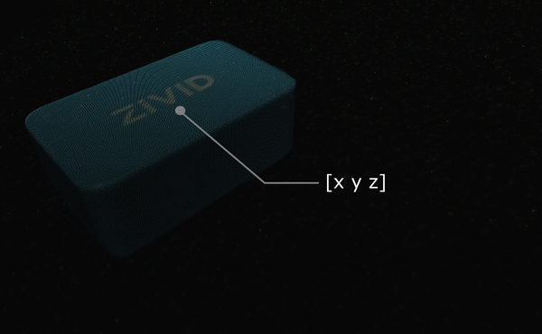
Zivid 포인트 클라우드에서 머신 비전 소프트웨어를 실행한다고 가정해 보겠습니다. 이것은 이 Zivid gem과 같은 관심의 대상을 감지하고 그것의 위치를 추정합니다. 선택 지점을 설명하는 x, y, z 값은 Zivid 카메라의 좌표계를 기준으로 제공됩니다.
팁
애플리케이션을 실행하기 전에 핸드-아이 칼리브레이션과 동일한 캡처 주기를 사용하여 카메라를 Warm-up 하는 것이 좋습니다. 온도 의존적 성능 요인의 영향을 더욱 줄이려면 Thermal Stabilization 을 활성화하세요.
어떤 경우에는 알고리즘이 롤, 피치 및 요 각도같은 객체의 방향도 출력합니다. 이런 매개변수는 Zivid 카메라의 좌표계를 기준으로 제공됩니다.
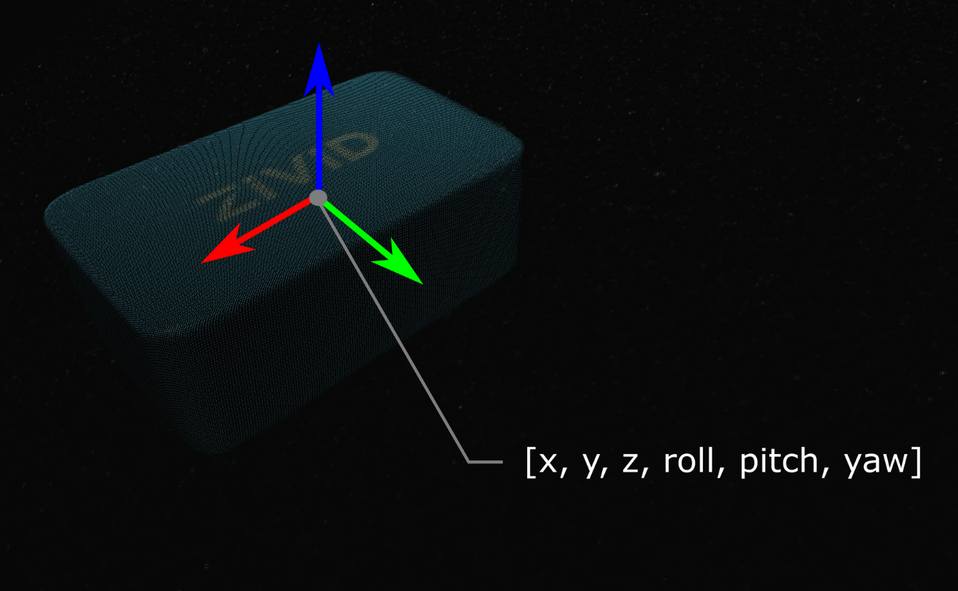
객체의 자세(위치 및 방향)는 Homogeneous Transformation Matrix로 설명할 수 있습니다. (로봇) 자세 및 좌표계에 익숙하지 않은 경우 Position, Orientation and Coordinate Transformations 을 확인하십시오.
실제로 가장 쉬운 방법은 카메라의 포인트 클라우드를 로봇 베이스 기준 좌표계로 변환하는 것입니다. Zivid SDK는 데이터가 CPU에 복사되기 전에 transforming 기능을 지원하므로 매우 빠릅니다.
아래에서는 카메라에서 로봇 베이스 기준 좌표계로 단일 점 또는 전체 점군을 변환하는 수학적 이론을 살펴보겠습니다. 이어서 이를 실제로 적용하는 방법을 보여주는 코드 튜토리얼이 제공됩니다.
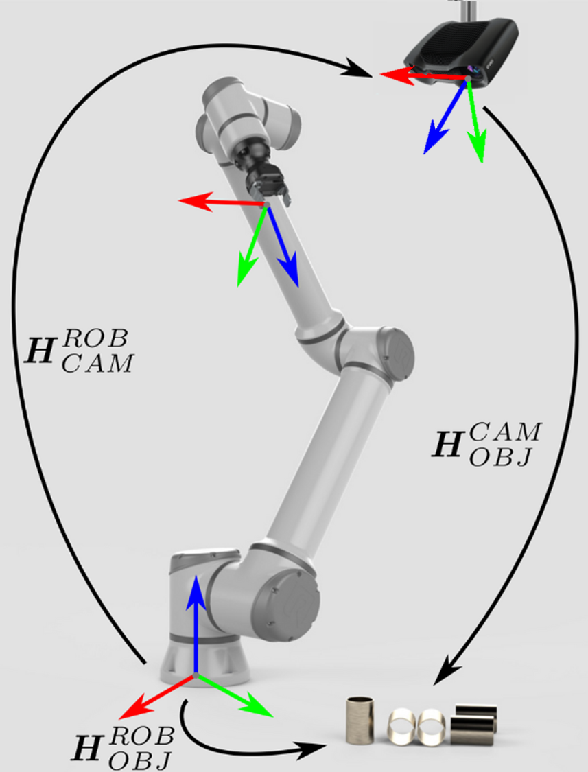
Eye-to-hand 시스템을 다루는 경우 단일 3D 포인트를 Zivid 카메라에서 로봇 베이스 좌표계로 변환하는 방법은 다음과 같습니다.
전체 Zivid 포인트 클라우드를 카메라 좌표계에서 로봇 베이스 좌표계로 변환하려면 포인트 클라우드의 각 포인트에 위의 방정식을 적용하십시오.
반면에 Zivid 카메라를 기준으로 개체의 포즈를 변환하려면 다음 방정식을 적용합니다.
포즈가 Homogeneous Transformation Matrix로 표현되어 있다고 가정합니다. 그렇지 않은 경우 다음 기사를 확인하십시오. Conversions Between Common Orientation Representations.
결과 포즈는 로봇 TCP(Tool Center Point)가 피킹을 위해 달성해야 하는 포즈입니다. TCP와 로봇 플랜지 사이의 오프셋은 로봇 측에서 고려해야 합니다.
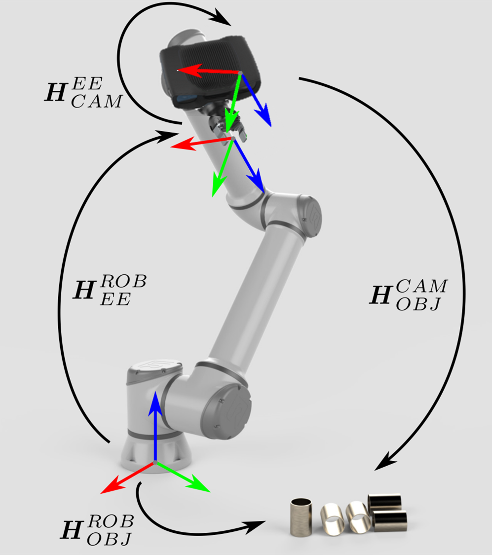
Eye-in-hand 시스템에 대한 접근 방식도 비슷합니다. 차이점은 로봇의 현재 자세가 방정식에 포함되어야 한다는 것입니다. 다른 포즈와 마찬가지로 로봇 포즈가 Homogeneous Transformation Matrix로 표현된다고 가정합니다. 로봇 포즈가 다르게 표현되는 경우 다음 기사를 확인하세요. Conversions Between Common Orientation Representations.
다음 방정식은 단일 3D 포인트를 Zivid 카메라에서 로봇 베이스 좌표계로 변환하는 방법을 설명합니다.
전체 Zivid 포인트 클라우드를 카메라 좌표계에서 로봇 베이스 좌표계로 변환하려면 포인트 클라우드의 각 포인트에 위의 방정식을 적용하십시오.
Zivid 카메라를 기준으로 개체의 포즈를 변환하려면 다음 방정식을 사용합니다.
결과 포즈는 로봇 TCP(Tool Center Point)가 피킹을 위해 달성해야 하는 포즈입니다. TCP와 로봇 플랜지 사이의 오프셋은 로봇 측에서 고려해야 합니다.
이 이론을 실제로 적용하기 위해 튜토리얼을 따라 카메라의 단일 지점이나 전체 지점 클라우드를 로봇 기본 참조 프레임으로 변환해 보겠습니다.
"""
Transform single data point or entire point cloud from camera to robot base reference frame using Hand-Eye calibration
matrix.

This example shows how to utilize the result of Hand-Eye calibration to transform either (picking) point coordinates
or the entire point cloud from the camera to the robot base reference frame.

For both Eye-To-Hand and Eye-In-Hand, there is a Zivid gem placed approx. 500 mm away from the robot base (see below).
The (picking) point is the Zivid gem centroid, defined as image coordinates in the camera reference frame and hard-coded
in this code example. Open the ZDF files in Zivid Studio to inspect the gem's 2D and corresponding 3D coordinates.

Eye-To-Hand
- ZDF file: ZividGemEyeToHand.zdf
- 2D image coordinates: (1035,255)
- Corresponding 3D coordinates: (37.77 -145.92 1227.1)
- Corresponding 3D coordinates (robot base reference frame): (-12.4  514.37 -21.79)

Eye-In-Hand:
- ZDF file: ZividGemEyeInHand.zdf
- 2D image coordinates: (1460,755)
- Corresponding 3D coordinates (camera reference frame): (83.95  28.84 305.7)
- Corresponding 3D coordinates (robot base reference frame): (531.03  -5.44 164.6)

For verification, check that the Zivid gem centroid 3D coordinates are the same as above after the transformation.

The YAML files for this sample can be found under the main instructions for Zivid samples.

"""
먼저, 로봇 기본 기준 프레임에서 카메라 포즈를 얻습니다(eye-to-hand의 교정 결과).
포인트 클라우드는 카메라 참조 프레임에 제공됩니다.
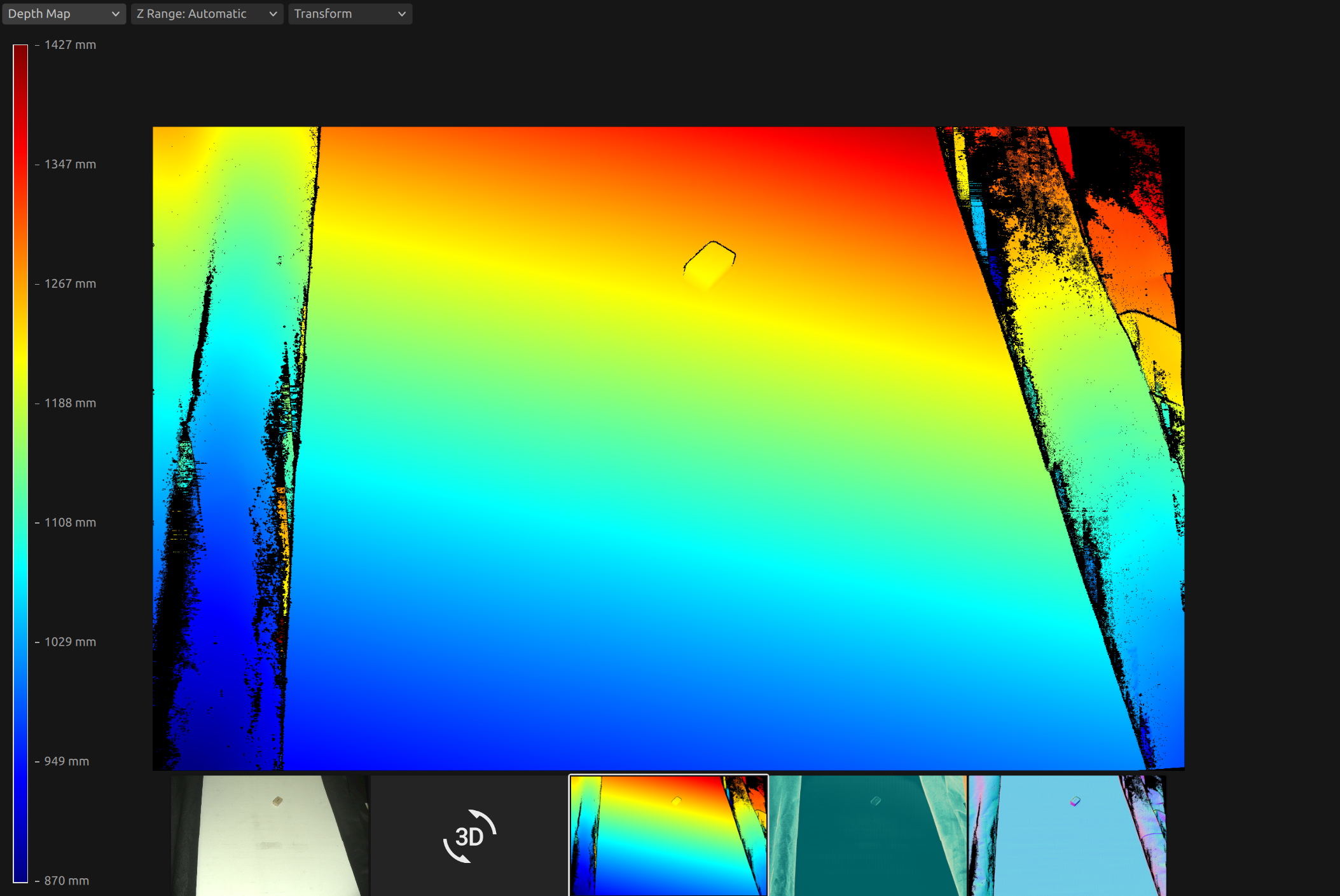
이 시점에서 머신 비전 소프트웨어는 작업물을 감지하고 피킹 지점을 추정해야 합니다. 이 예시에서는 피킹 지점이 알려져 있으며, 카메라 기준 프레임의 이미지 좌표로 정의된다고 가정합니다.
로봇 베이스 기준 좌표계에서 피킹 지점은 다음과 같이 계산됩니다. 먼저 포인트 클라우드를 얻습니다.
먼저, 다음과 같은 포즈를 취합니다.
플랜지(엔드 이펙터) 기준 프레임의 카메라 포즈(eye-in-hand의 교정 결과)
로봇 기반 참조 프레임의 플랜지(엔드 이펙터) 포즈(현재 로봇 포즈)
eye_in_hand_transform_file_path = get_sample_data_path() / "EyeInHandTransform.yaml"
robot_transform_file_path = get_sample_data_path() / "RobotTransform.yaml"

print("Reading camera pose in flange (end-effector) reference frame (result of eye-in-hand calibration)")
flange_to_camera_transform = load_and_assert_affine_matrix(eye_in_hand_transform_file_path)

print("Reading flange (end-effector) pose in robot base reference frame")
base_to_flange_transform = load_and_assert_affine_matrix(robot_transform_file_path)
이 두 변환 행렬을 곱하면 로봇 기본 참조 프레임에서 카메라 포즈를 얻습니다.
포인트 클라우드는 카메라 참조 프레임에 제공됩니다.
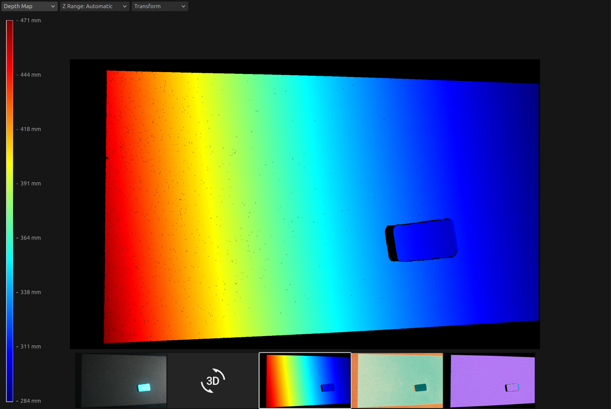
이 시점에서 머신 비전 소프트웨어는 작업물을 감지하고 피킹 지점을 추정해야 합니다. 이 예시에서는 피킹 지점이 알려져 있으며, 카메라 기준 프레임의 이미지 좌표로 정의된다고 가정합니다.
로봇 베이스 기준 좌표계에서 피킹 지점은 다음과 같이 계산됩니다. 먼저 포인트 클라우드를 얻습니다.
그런 다음 포인트 클라우드에서 카메라 참조 프레임의 선택 지점(XYZ 좌표)을 얻습니다.
print("Transforming single point")

xyz = point_cloud.copy_data("xyz")

point_in_camera_frame = np.array(
    [
        xyz[image_coordinate_y, image_coordinate_x, 0],
        xyz[image_coordinate_y, image_coordinate_x, 1],
        xyz[image_coordinate_y, image_coordinate_x, 2],
        1,
    ]
)
print(f"Point coordinates in camera reference frame: {point_in_camera_frame[0:3]}")
마지막으로, 피킹 포인트를 로봇 기본 참조 프레임으로 변환합니다.
피킹 지점만 변환하는 대신, 포인트 클라우드 전체를 로봇 베이스 기준 좌표계로 변환할 수 있습니다. 이를 통해 머신 비전 소프트웨어는 포인트 클라우드에서 로봇 베이스 기준 좌표계의 피킹 지점을 직접 찾을 수 있습니다.
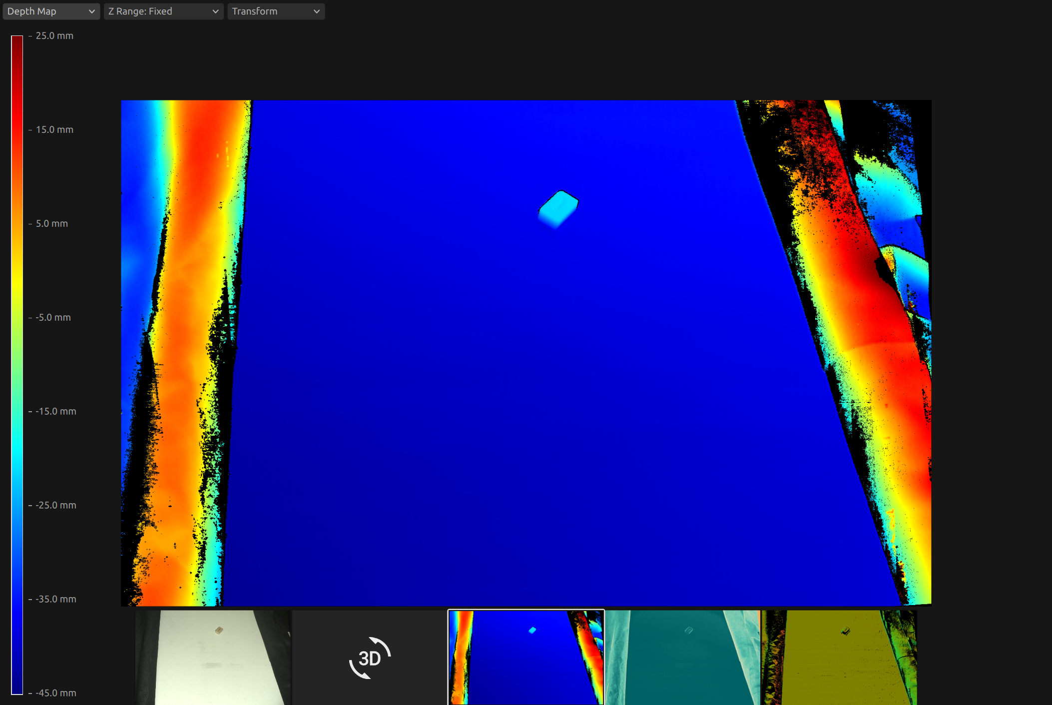
ZDF 형식의 포인트 클라우드를 얻으려면 코드 샘플을 실행하거나 Sample Data (ZividGemEyeToHandInRobotBaseFrame.zdf)의 일부로 다운로드할 수 있습니다.
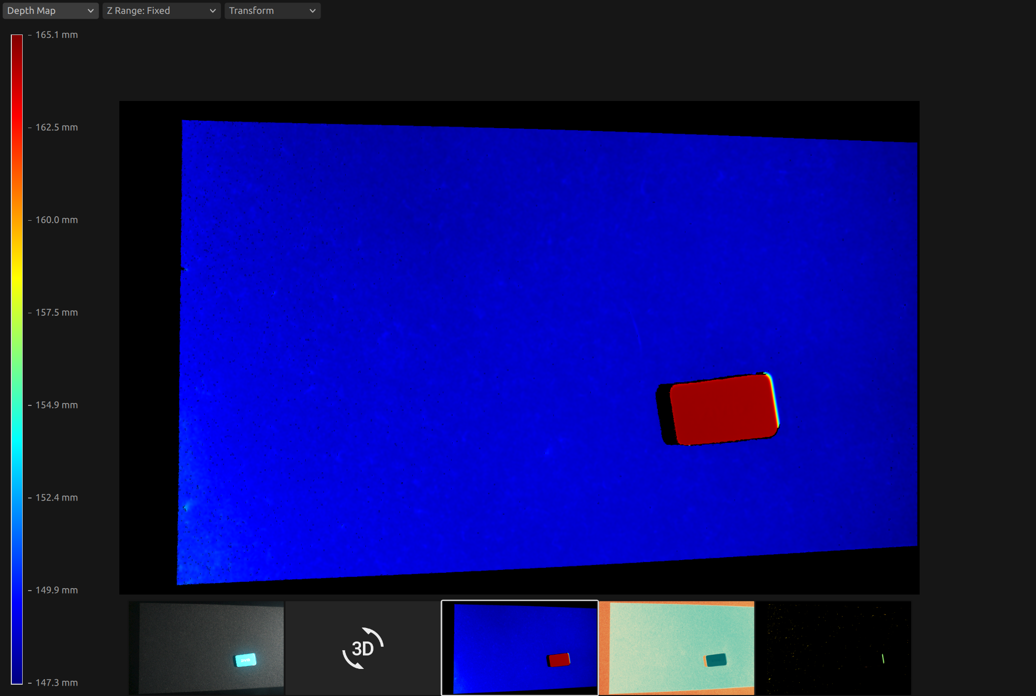
ZDF 형식의 포인트 클라우드를 얻으려면 코드 샘플을 실행하거나 Sample Data (ZividGemEyeInHandInRobotBaseFrame.zdf)의 일부로 다운로드할 수 있습니다.
Version History
SDK |
Changes |
|---|---|
2.12.0 |
핸드-아이 칼리브레이션 결과를 활용해 Zivid 카메라 좌표계에서 로봇 기반 좌표계로 객체 좌표를 변환하는 방법에 대한 섹션을 추가합니다. |
