使用 HALCON 进行手眼标定
To perform hand-eye calibration with HALCON, collect matching robot pose and calibration-object pose pairs, then compute the transformation with HALCON's hand_eye_calibration operator.
介绍
This guide describes how to integrate hand-eye calibration using Halcon with Zivid cameras. It is generally recommended to use the Hand-Eye GUI for hand-eye calibration, but this guide provides an alternative approach using HALCON and HDevelop. The operators can also be used in HALCON's C++ and C# interfaces. Sample code in HDevelop can be found in our samples repository:
EyeInHandCalibration3DObject.hdev - 使用 Zivid 相机和 3D 标定对象进行手眼标定
EyeInHandCalibrationMVTecPlate.hdev - 使用 Zivid 相机和 MVTec 标定板进行手眼标定
Sample Data - 使用 HALCON 运行手眼标定示例所需的示例数据集
运行 HDevelop 示例需要示例数据(sample data),也可以用您自己的数据替换它。
MVTec 文档/手眼标定问题的原理及 HALCON
MVTec 提供了相关文档,其中涵盖了手眼标定和机器视觉方面更多的细节和具体信息。手眼标定的文档概述在 Solution Guide III-C: 3D Vision 中,相关章节是 Chapter 8: Robot Vision 。
实现手眼标定的方法有很多种。虽然没有一种方法是完美的,但具体选择哪种方法取决于具体的应用场景和需求。从原理上讲,它们的基本原理是相似的。目标是找到相机坐标系与机器人基座或机器人法兰坐标系之间的齐次变换关系。由于 Zivid 相机采集的数据是三维的,因此可以根据相机在机器人基座坐标系中的位姿计算出该变换。更多信息请参阅 手眼标定的原理 。
有关如何使用 HALCON/HDevelop 的信息,您还可以参考页面 如何运行 HALCON 示例 。
先决条件
Zivid 相机
已安装 HALCON 软件
请查看 github 上的示例: zivid-halcon-samples
下载 示例数据
3D 标定对象或 HALCON 标定板
已知位姿参数(例如欧拉角 XYX 等)的机器人
理解 手眼标定的概念
相机设置
In general we recommend using preset settings wherever possible. This also applies for hand-eye calibration. Using the same settings for hand-eye calibration and for the application itself gives the best possible performance. In the sample data the manufacturing presets were used. If you are struggling with your settings, see Camera Settings for Hand-Eye Calibration.
标定对象
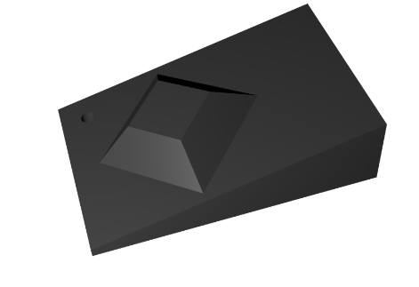
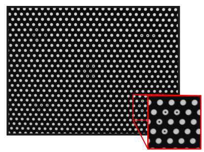
为了在两个坐标系之间执行手眼标定,我们需要一组在这两个坐标系中均具有对应关系的位姿或点集。为了生成对应的位姿/点,必须使用标定对象。更多详细信息请参阅 标定对象 页面。您可以选择使用 HALCON 标定板,也可以使用具有已知几何形状且无对称性的 3D 标定对象。
备注
由于 Zivid 相机捕获的数据是 3D 的,因此 无需 使用依赖于 2D 相机内参的手眼标定方法。
机器人位姿
每家机器人制造商,甚至同一制造商的不同机器人型号,往往都有各自独特的机器人位姿表示与导出方式。虽然笛卡尔坐标系中的位置通常统一表示为 X、Y 和 Z(遵循右手坐标系规则),但方向的表示方法却多种多样。特别是欧拉角,其参数化方式存在多种变体,因此明确机器人所采用的具体约定至关重要。相比之下,四元数和齐次变换矩阵由于具有唯一且无歧义的特性,处理起来更为简便,但可能无法获取。
HALCON 支持多种位姿方向表示方法,并提供了在不同表示法之间进行转换的功能。这些细节在 create_pose 算子的文档中有详细说明。你可以使用 pose_to_hom_mat3d 算子将机器人位姿转换为齐次变换矩阵。关于位姿的数学描述,您可以查看 位姿转换 文档。
记录机器人位姿的方法有多种。但遗憾的是,HALCON 并未提供针对任何机器人制造商的直接接口,因此用户需要通过套接字(socket)连接或其他通信接口自行编程实现数据交互。在我们的示例中,我们采用了手动记录机器人位姿并将其输入到 HALCON 中的方式。
手眼标定过程
在开始标定过程之前,请确保:
相机已经 预热
在所有机器人位姿下,标定对象都必须始终处于相机的视场范围内。
手眼标定步骤
手眼标定过程包括以下步骤:
从多个机器人配置中捕获标定对象位姿
检测每幅图像中的标定对象特征
录入对应的机器人末端执行器位姿
保存 3D 场景和机器人位姿对
无论是执行眼在手上(eye-in-hand)标定还是眼在手外(eye-to-hand)标定,其流程基本相似,均包含上述步骤。两者的区别在于:在 eye-in-hand 标定中,相机安装在机器人末端执行器上;而在 eye-to-hand 标定中,相机固定于环境中并观测机器人。因此,在 eye-in-hand 的情况下,标定对象是静止的;而在 eye-to-hand 的情况下,标定对象随机器人一起运动。在这两种情况下,都需要采集机器人在不同位姿下的标定对象的图像,这也意味着标定对象在相机视场中具有不同的位姿。
因此,对于数据收集而言,以下几点适用于两种情况:
将机器人移动到 10-20 个不同的位姿
确保多样化的观测视角与关节空间的充分利用
在每个位姿下捕获标定对象
从控制器记录机器人位姿
有关如何获得用于手眼标定的良好数据集的更多详细信息和技巧,请参阅 获取好的数据 。
在我们的示例中,点云数据在 ZividStudio 中采集,然后导出为 *.zdf 和 *.ply(包含法线)文件,相应的机器人位姿则保存为文本文件。*.zdf 文件用于提取估计的内参。*.ply 文件用于捕获每幅图像中标定对象的位姿。
备注
由于 HALCON 使用法线来估计标定对象的位姿,因此确保导出的点云文件中包含法线非常重要。
为了进行验证和调试,建议保存捕获和位姿对的数据集。
相机内参
使用 HALCON 标定板时,我们建议加载从 HALCON 采集的标定板的 ZDF 文件中获取的内参。更多信息可在知识库的 相机内参 章节中查阅。使用 ZDF 文件及我们提供的相应 Python 脚本将内参保存为 HALCON 格式后,可以按照以下方式加载内参。
read_cam_par(ZividDataDir + '/ZividHandEyeHalconData/estimated_intrinsics.dat', InputCameraParameters)
特征提取
使用 HALCON 标定板时,可以使用 find_calib_object 算子从每张采集的图像中提取标定对象的位姿。
create_calib_data ('hand_eye_moving_cam', 1, 1, CalibDataID)
set_calib_data_calib_object (CalibDataID, 0, CalibrationPlateFile)
find_calib_object (GrayImage, CalibDataID, 0, 0, I, ['sigma'], [2])
使用 3D 标定物对象时,需要在每个捕获的场景中确定标定对象的位姿。从每张捕获的图像中提取标定对象特征,以建立多视角下的点对应关系。为了提取标定对象的位姿,可以使用 create_surface_model 和 find_surface_model 算子。
create_surface_model (ObjectModel3DCalibrationObject, 0.03, [], [], SurfaceModelID)
find_surface_model (SurfaceModelID, ObjectModel3DScene, 0.05, 0.2, 0, 'false', [], [], PoseObject, Score, SurfaceMatchingResultID)
计算变换关系
Now in HALCON we collect pose pairs of the calibration object and the robot. We add these pairs to a calibration data model with the operators set_calib_data_observ_pose and set_calib_data.
create_calib_data ('hand_eye_moving_cam', 0, 0, CalibDataID)

for j := 1 to NumberOfCaptures by 1
    set_calib_data_observ_pose (CalibDataID, 0, 0, j, PoseObjects[j])
    set_calib_data (CalibDataID, 'tool', j, 'tool_in_base_pose', RobotPoses[j])
endfor
一旦完成收集机器人位姿和标定对象位姿对,就可以使用 HALCON 的 hand_eye_calibration 算子计算变换关系。
calibrate_hand_eye (CalibDataID, Errors)
验证
标定完成后,通过以下方式验证结果:
检查每个标定位姿的残差
使用机器人执行 触碰测试
目视检查点云对齐情况
这可以在 HALCON/HDevelop 中使用运算符和 3D 可视化方法完成。还可以将获得的齐次变换矩阵与从 Hand-Eye GUI 中获得的矩阵进行比较。有关评估标定质量的更多信息,请参阅 手眼标定的验证 。
Next Steps
请继续阅读 如何使用手眼标定结果 以了解如何应用您的手眼标定结果。