Zivid 标定对象
Zivid 支持以下标定对象:
Zivid 标定板
ArUco 标记
Zivid Calibration Boards
主要的 Zivid 标定板可以在 Zivid WebShop 购买。这些标定板也可用于通过 Infield Correction 进行相机维护。要在手眼标定中使用该标定板,每次捕获中都需要能够检测到棋盘格和 ArUco 标记。
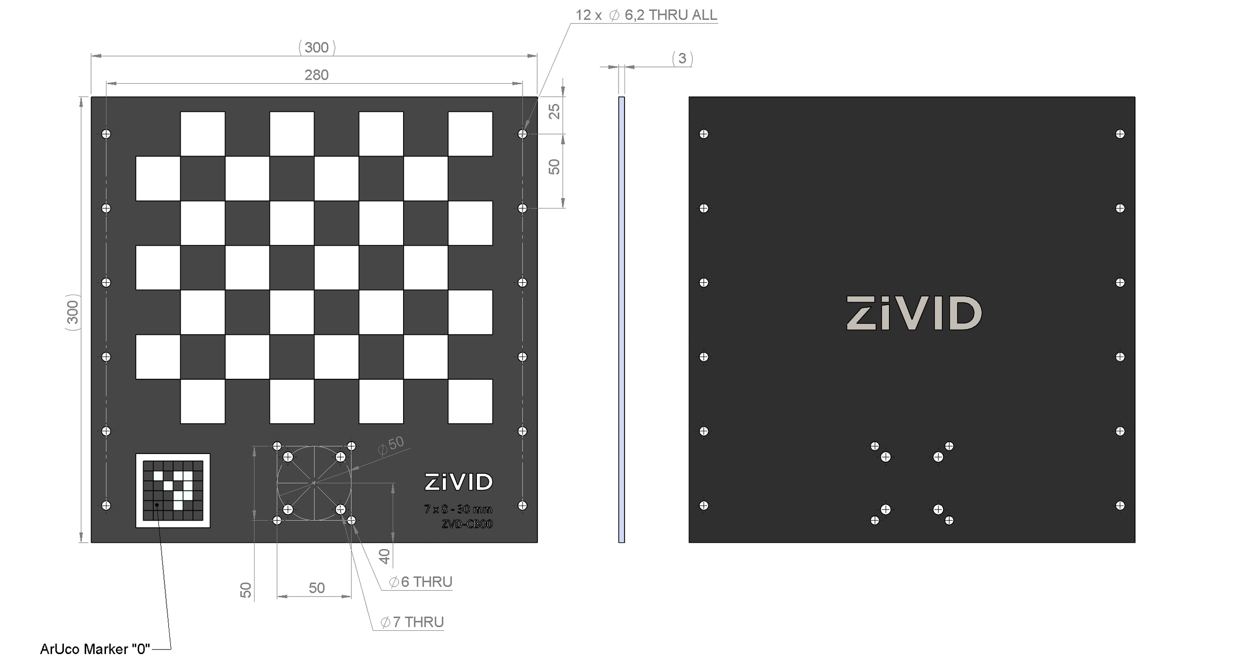
标定板的 CAD 文件可以从 CAD Downloads 下载。
位姿检测
棋盘格检测返回的位姿的原点位于棋盘格左上角的内角点,坐标轴方向如下图所示。
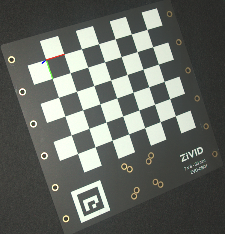
要估计位姿,请检测棋盘格并从检测结果中读取位姿。

std::cout << "Detecting and estimating pose of the Zivid checkerboard in the camera frame" << std::endl;
const auto detectionResult = Zivid::Calibration::detectCalibrationBoard(frame);
if(!detectionResult.valid())
{
    throw std::runtime_error("No checkerboard detected. " + detectionResult.statusDescription());
}
const auto cameraToCheckerboardTransform = detectionResult.pose().toMatrix();
Console.WriteLine("Detecting and estimating pose of the Zivid checkerboard in the camera frame");
var detectionResult = Detector.DetectCalibrationBoard(frame);
var cameraToCheckerboardTransform = new Zivid.NET.Matrix4x4(detectionResult.Pose().ToMatrix());
print("Detecting and estimating pose of the Zivid checkerboard in the camera frame")
detection_result = zivid.calibration.detect_calibration_board(frame)

if not detection_result.valid():
    raise RuntimeError(f"No Checkerboard detected. {detection_result.status_description()}")

camera_to_checkerboard_transform = detection_result.pose().to_matrix()
上图是通过将位姿投影到 2D 图像上并绘制坐标系轴线而生成的。
std::cout << "Converting to OpenCV image format" << std::endl;
const auto bgraImage = pointCloudToColorBGRA_SRGB(pointCloud);
std::cout << "Visualizing checkerboard with coordinate system" << std::endl;
cv::Mat bgrCoordinateSystem;
cv::cvtColor(bgraImage, bgrCoordinateSystem, cv::COLOR_BGRA2BGR);
drawCoordinateSystem(frame, cameraToCheckerboardTransform, bgrCoordinateSystem);
displayBGR(bgrCoordinateSystem, "Checkerboard transformation frame");
print("Converting to OpenCV image format")
bgra_image = point_cloud.copy_data("bgra_srgb")
print("Visualizing checkerboard with coordinate system")
bgr_coordinate_system = bgra_image[:, :, 0:3].copy()
_draw_coordinate_system(frame, camera_to_checkerboard_transform, bgr_coordinate_system)
display_bgr(bgr_coordinate_system, "Checkerboard transformation frame")
如需查看完整示例,请参阅 基于棋盘格的坐标转换 。
ArUco Markers
Zivid 手眼标定可以使用一个或多个 ArUco 标记作为标定对象。一般来说,使用的标记越多越好。您可以在 https://chev.me/arucogen/ 生成和打印 ArUco 标记。确保标记打印在平坦的表面上。我们支持的 OpenCV 字典包括 4x4、5x5、6x6 和 7x7 图案。使用 ArUco 标记进行手眼标定的一个好处是它们尺寸很小。另一个好处是,在每次捕获中并非所有标记都需要可检测到。

ArUco 标记需要多大?
我们建议在最远的成像距离处,每个 ArUco 位上至少有 7 个像素。下图显示了 ArUco 标记的放大图像,其中每个 ArUco 位由 8 个像素表示。以下示例解释了如何确定所需的最小尺寸(以毫米为单位)。
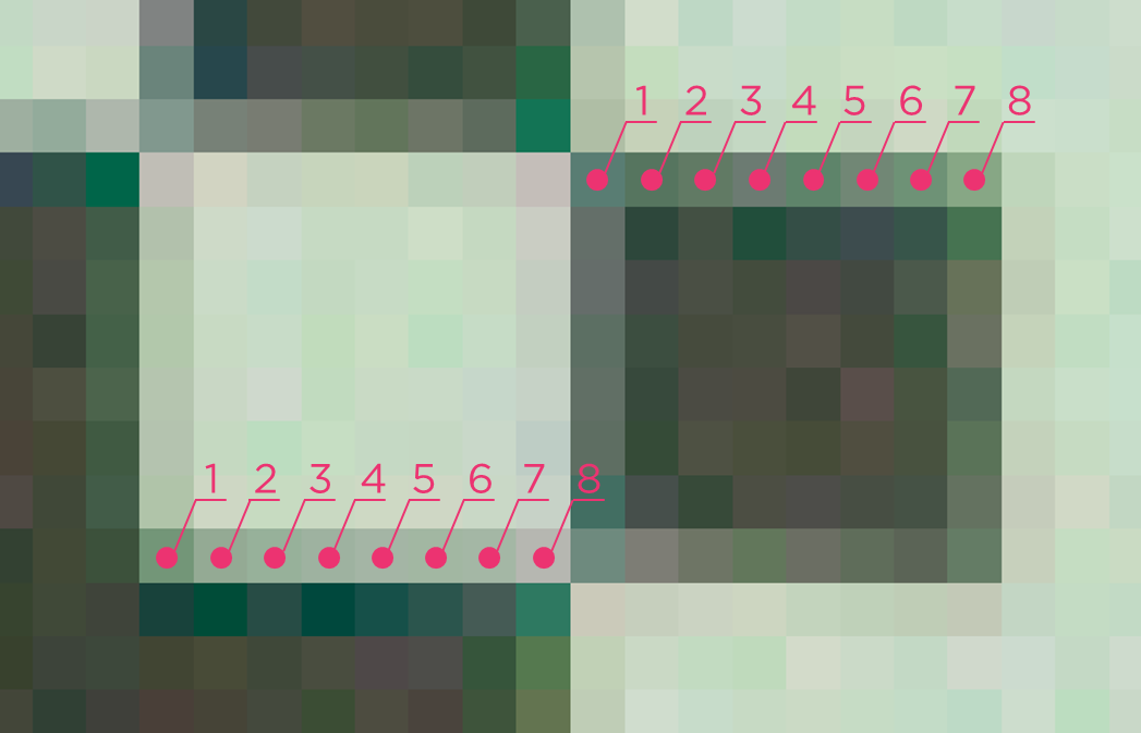
对于 4x4 ArUco 字典,有 6 位(4 个内部位和 2 个外部位),因此每个标记的边至少应有 42 个像素。
假设您使用的是 Zivid 2+ M130 相机,最大成像距离为 2 米。此时相机的空间分辨率为 0.5 毫米(请参阅 计算 FOV 和成像距离 )。将 0.5 毫米乘以 42 像素可得出 21 毫米。
因此,要在最远 2 米的距离内使用 Zivid 2+ M130,ArUco 标记的尺寸至少应为 21 毫米。
备注
您应该在 ArUco 标记周围留出一些空白,至少留出 1 位边框。对于上例,这意味着每边留出 3.5 毫米(7 个像素乘以 0.5 毫米)。
多个 ArUco 标记应如何排列?
在自定义目标上同时安装多个标记时:
将标记排列成真正的 2D 图案,例如十字形或网格状,而不是排列成一条直线。用于手眼标定的任何 3 个或更多标记都应覆盖实际的 2D 区域,而不是位于(或接近)一条直线上。
避免将螺钉、支架、夹具或线缆等安装硬件放置在可能从某些视角遮挡标记视野、而在其他视角不遮挡的位置。如果某个标记在多个位姿中持续被遮挡,即使平移残差看起来仍然良好,也可能导致旋转残差过大或无效。
有关此情况出错时的示例,请参阅 不满意的 Hand-Eye Calibration(手眼标定)结果(多标记 ArUco 目标:平移良好,旋转为 NaN 或极端值) 。
位姿检测
ArUco 标记检测返回的位姿的原点位于标记的中心。其 z 轴垂直指向标记表面,如下图所示。
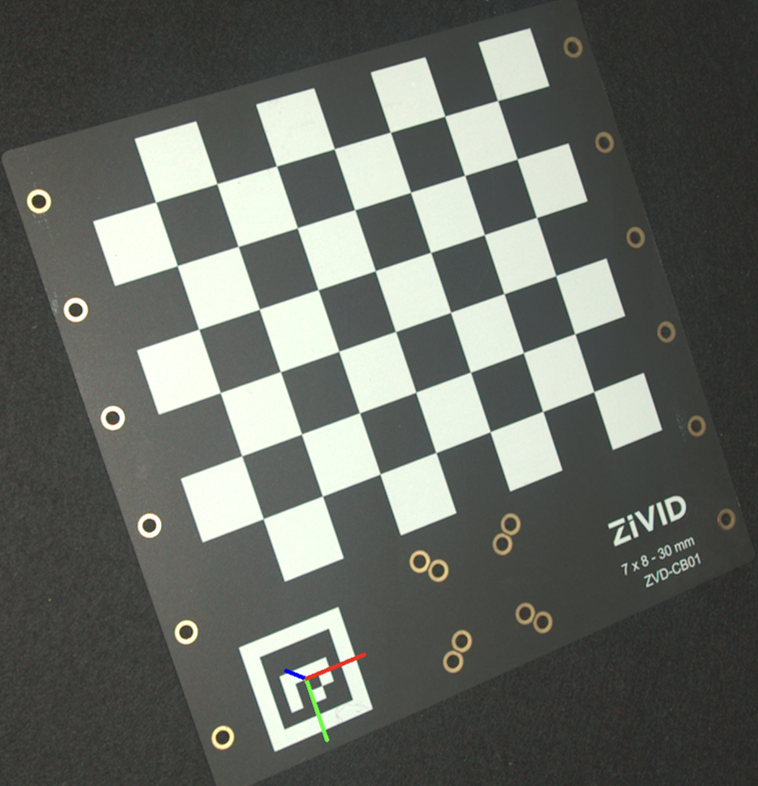
要估计位姿,请检测标记并从检测到的标记中读取位姿。
std::cout << "Detecting ArUco marker" << std::endl;
const auto detectionResult = Zivid::Calibration::detectMarkers(frame, markerId, markerDictionary);
std::cout << "Estimating pose of detected ArUco marker" << std::endl;
const auto cameraToMarkerTransform = detectionResult.detectedMarkers()[0].pose().toMatrix();
Console.WriteLine("Detecting ArUco marker");
var detectionResult = Detector.DetectMarkers(frame, markerId, markerDictionary);
Console.WriteLine("Estimating pose of detected ArUco marker");
var cameraToMarkerTransform = new Zivid.NET.Matrix4x4(detectionResult.DetectedMarkers()[0].Pose().ToMatrix());
上图是通过将位姿投影到 2D 图像上并绘制坐标系轴线而生成的。
std::cout << "Converting to OpenCV image format" << std::endl;
const auto bgraImage = pointCloudToColorBGRA_SRGB(pointCloud);
std::cout << "Visualizing ArUco marker with coordinate system" << std::endl;
cv::Mat bgrCoordinateSystem;
cv::cvtColor(bgraImage, bgrCoordinateSystem, cv::COLOR_BGRA2BGR);
drawCoordinateSystem(frame, cameraToMarkerTransform, bgrCoordinateSystem);
displayBGR(bgrCoordinateSystem, "ArUco marker transformation frame");
print("Converting to OpenCV image format")
bgra_image = point_cloud.copy_data("bgra_srgb")
print("Visualizing ArUco marker with coordinate system")
bgr_coordinate_system = bgra_image[:, :, 0:3].copy()
_draw_coordinate_system(frame, camera_to_marker_transform, bgr_coordinate_system)
display_bgr(bgr_coordinate_system, "ArUco marker transformation frame")
如需查看完整示例,请参阅 基于 ArUco 标记的坐标转换 。
应该使用哪种标定对象?
我们建议尽可能使用 Zivid 标定板。请根据您使用的相机型号选择标定板型号,如下表所示:
相机型号 |
推荐的标定板 |
|---|---|
Zivid 2 M70 |
7x8 - 30 mm |
Zivid 2 L100 |
7x8 - 30 mm |
Zivid 2+ MR130 |
7x8 - 30 mm |
Zivid 2+ LR110 |
7x8 - 30 mm |
Zivid 2+ MR60 |
5x6 - 20 mm |
Zivid 3 XL250 |
7x8 - 30 mm |
ArUco 标记适用于以下使用场景:
眼在手外(Eye-to-hand)的配置
标定对象需要永久安装在机器人上
Zivid 标定板尺寸过大
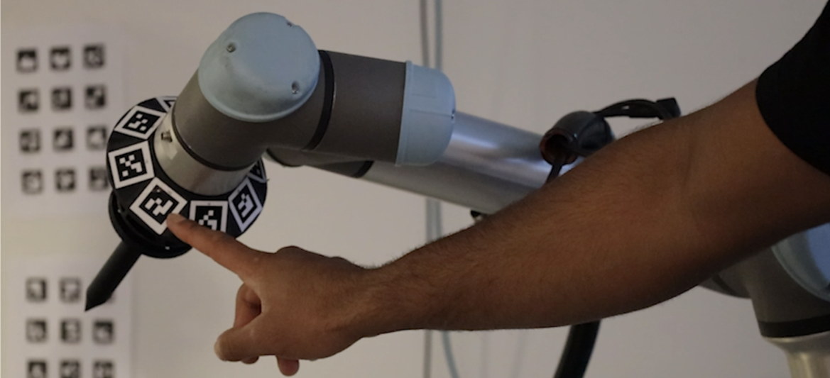
现在您已经选择了标定对象,请查看 如何运行和集成 Zivid 手眼标定 。
版本历史
SDK |
变更 |
|---|---|
2.18.0 |
改进了 ArUco 标记检测。 |
2.16.0 |
增加了对较小尺寸的标定板 ZVDA-CB02 (5x6 20 mm) 的支持。 |
2.14.0 |
取消了对 9x6 灰白棋盘格的支持。 |
2.13.0 |
增加了对 ArUco 标记的支持。 |