ハンドアイキャリブレーション結果の使い方
この記事では、 Zivid カメラの座標系からロボットのベース座標系へ、対象物の座標を変換する方法について説明します。
以下の条件を満たしていることを前提とします。
Zivid カメラを伴ったロボット
ロボットを物体まで誘導するマシンビジョンソフトウェア
既にハンドアイキャリブレーションを実施済み
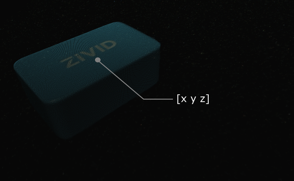
Zivid の点群に対してマシンビジョンソフトウェアを実行するとします。このソフトウェアは、 Zivid の宝石(下図参照)などの対象物を検出し、その位置を推定します。検出点を表す x、y、z の値は、 Zivid カメラの座標系を基準として与えられます。
Tip
アプリケーションを実行する前に、ハンドアイキャリブレーションと同じキャプチャサイクルを使用してカメラを ウォームアップ することをお勧めします。温度に依存するパフォーマンス要因の影響をさらに軽減するには、 Thermal Stabilization が有効になっていることを確認してください。
場合によっては、アルゴリズムはオブジェクトの方向(ロール、ピッチ、ヨー角など)も出力します。これらのパラメータも、 Zivid カメラの座標系を基準として与えられます。
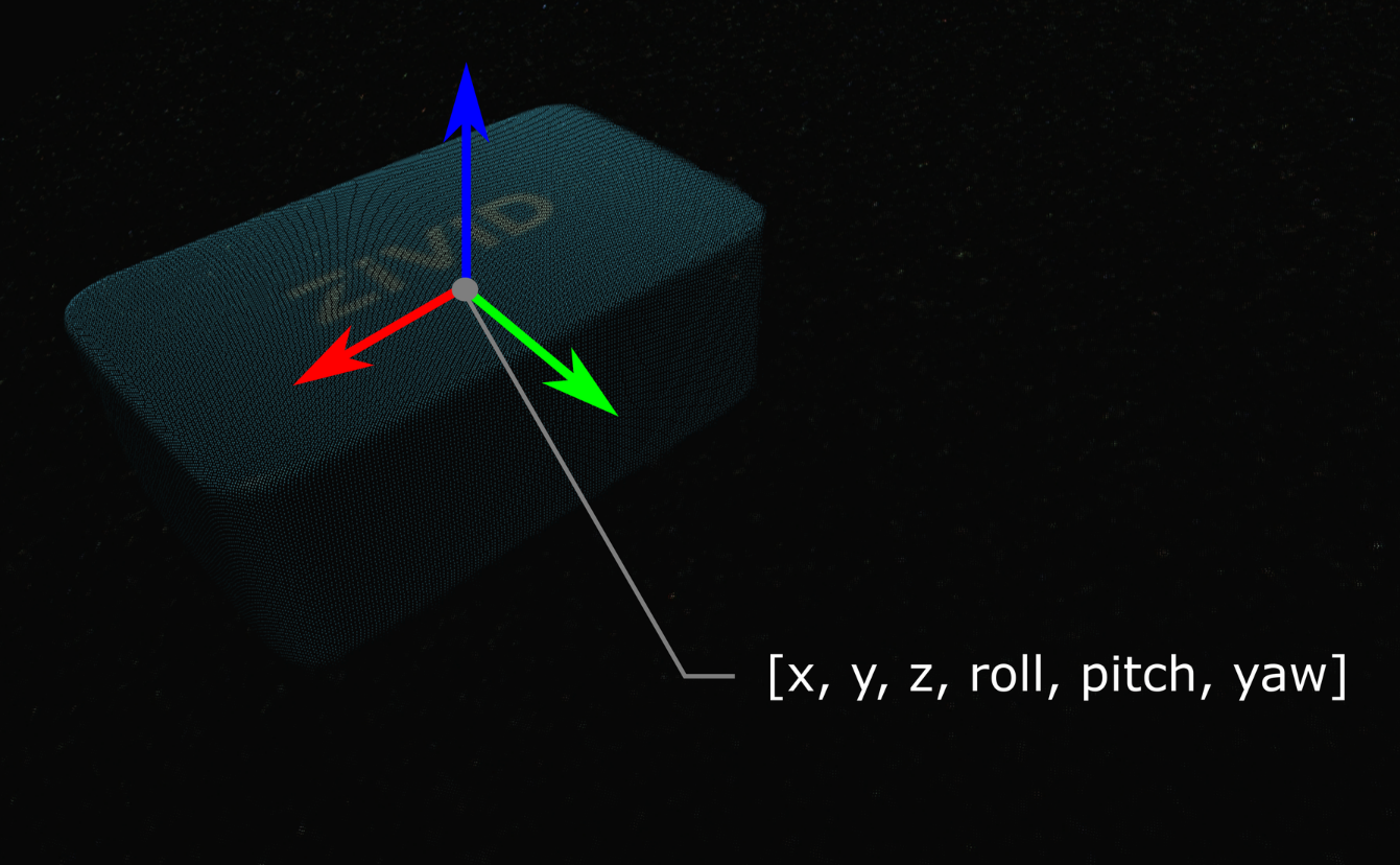
オブジェクトのポーズ(位置と向き)は、同次変換行列で記述することができます。(ロボットの)ポーズと座標系に詳しくない場合は、 位置、方向、座標変換 を確認してください。
実際には、最も簡単な方法は、カメラからの点群をロボットのベース参照フレームに変換することです。 Zivid SDK は、データを CPU にコピーする前に 変換 することをサポートしているため、非常に高速です。
以下に、カメラからの単一点または点群全体をロボットのベース参照フレームに変換する数学的理論を示します。この後に、これを実践するコードチュートリアルが続きます。
Eye-to-hand
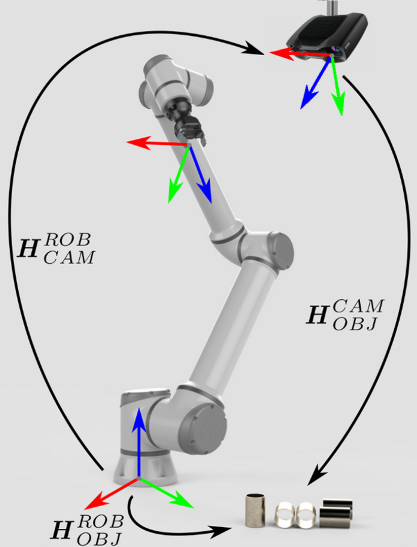
Eye-to-hand システムを扱っている場合、単一の 3D 点を Zivid カメラからロボットベース座標系に変換する方法は次のとおりです。
Zivid の点群全体をカメラ座標系からロボットベース座標系に変換するには、点群内の各点に上記の方程式を適用します。
一方、 Zivid カメラを基準にしてオブジェクトのポーズを変換するには、次の方程式を適用します。
ポーズは同次変換行列で記述されると仮定します。そうでない場合は、 一般的な方向表現間の変換 の記事を確認してください。
結果として得られるポーズは、ロボットのツール中心点(TCP)がピッキングのために達成する必要があるポーズです。 TCP とロボットのフランジの間のオフセットは、ロボット側で考慮する必要があります。
Eye-in-hand
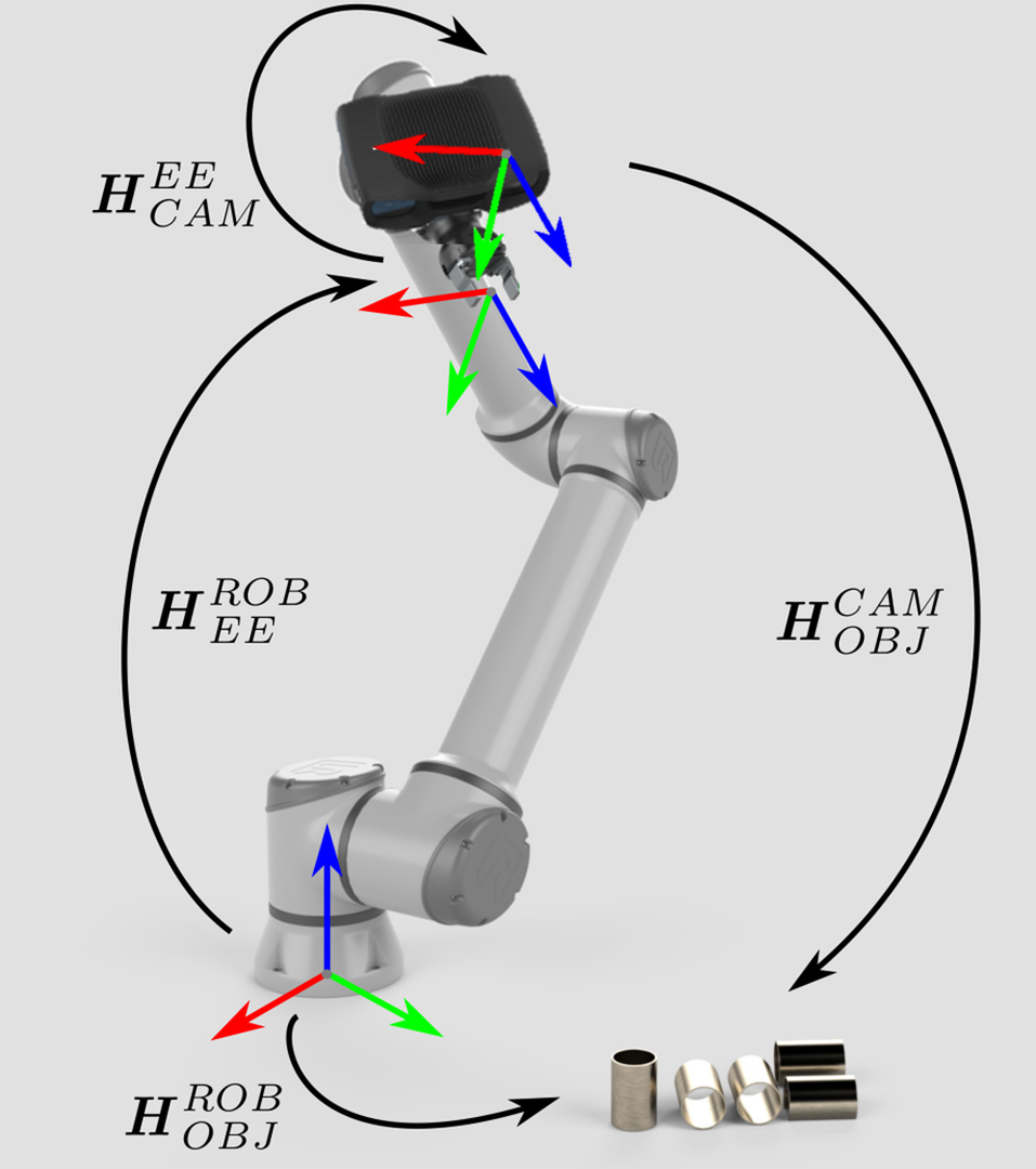
Eye-in-hand システムのアプローチも同様です。違いは、ロボットの現在の姿勢を方程式に含める必要があることです。他のポーズと同様に、ロボットのポーズは同次変換行列で表されると仮定します。ロボットのポーズが異なる方法で表現されている場合は、 一般的な方向表現間の変換 の記事を参照してください。
次の方程式は、単一の 3D 点を Zivid カメラからロボットベース座標系に変換する方法を示しています。
Zivid の点群全体をカメラ座標系からロボットベース座標系に変換するには、点群内の各点に上記の方程式を適用します。
Zivid カメラを基準にしてオブジェクトのポーズを変換するには、次の方程式を使用します。
結果として得られるポーズは、ロボットのツール中心点(TCP)がピッキングのために達成する必要があるポーズです。 TCP とロボットのフランジの間のオフセットは、ロボット側で考慮する必要があります。
この理論を実践するには、チュートリアルに従って、カメラからの単一点または点群全体をロボットベース参照フレームに変換しましょう。

"""
Transform a data point or entire point cloud from camera to robot base frame using the Hand-Eye calibration matrix.

This example shows how to utilize the result of Hand-Eye calibration to transform either (picking) point coordinates
or the entire point cloud from the camera to the robot base reference frame.

For both Eye-To-Hand and Eye-In-Hand, there is a Zivid gem placed approx. 500 mm away from the robot base (see below).
The (picking) point is the Zivid gem centroid, defined as image coordinates in the camera reference frame and hard-coded
in this code example. Open the ZDF files in Zivid Studio to inspect the gem's 2D and corresponding 3D coordinates.

Eye-To-Hand
- ZDF file: ZividGemEyeToHand.zdf
- 2D image coordinates: (1035,255)
- Corresponding 3D coordinates: (37.77 -145.92 1227.1)
- Corresponding 3D coordinates (robot base reference frame): (-12.4  514.37 -21.79)

Eye-In-Hand:
- ZDF file: ZividGemEyeInHand.zdf
- 2D image coordinates: (1460,755)
- Corresponding 3D coordinates (camera reference frame): (83.95  28.84 305.7)
- Corresponding 3D coordinates (robot base reference frame): (531.03  -5.44 164.6)

For verification, check that the Zivid gem centroid 3D coordinates are the same as above after the transformation.

The YAML files for this sample can be found under the main instructions for Zivid samples.

For more information on how to utilize Hand-Eye calibration results, check out this tutorial:
https://support.zivid.com/en/latest/camera/academy/applications/hand-eye/how-to-use-the-result-of-hand-eye-calibration.html

"""
Eye-to-hand
まず、ロボットベースの参照フレームでカメラのポーズを取得します(eye-to-hand キャリブレーションの結果)。
点群はカメラの参照フレームで与えられます。
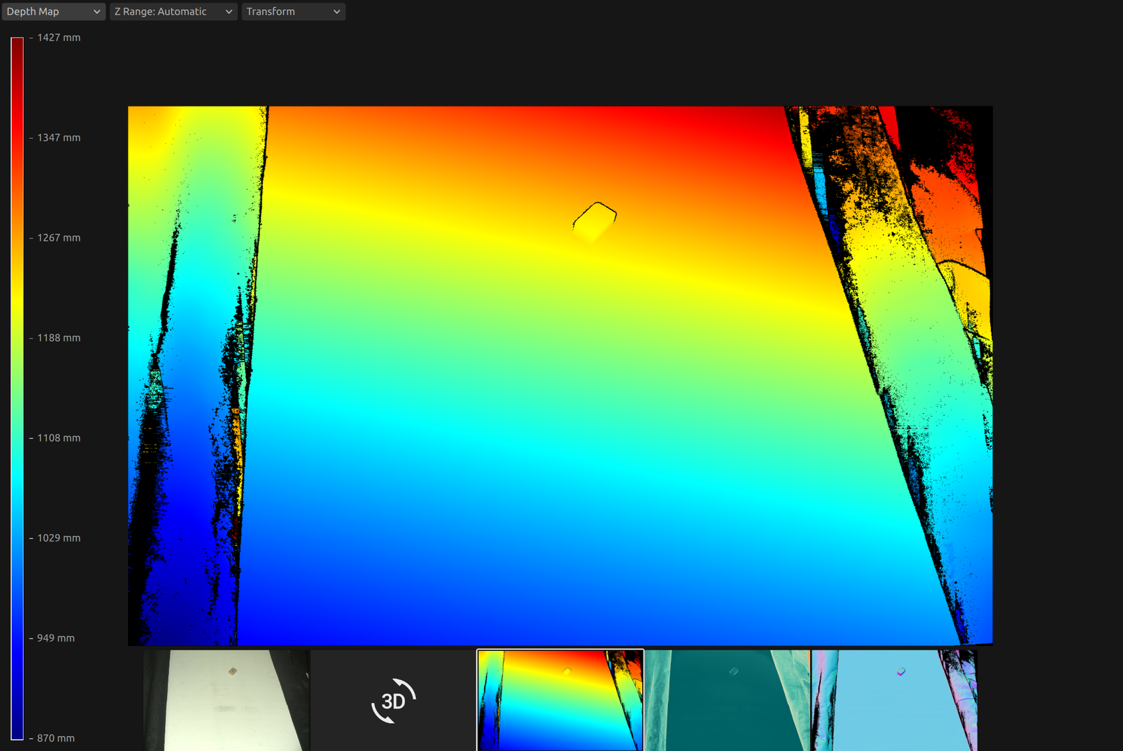
この時点で、マシンビジョンソフトウェアがワークピースを検出し、ピッキングポイントを推定する必要があります。この例では、ピッキングポイントが既知であり、カメラ参照フレーム内の画像座標として定義されていると仮定します。
ロボットベース参照フレーム内のピッキングポイントは次のように計算されます。まず点群を取得します。
Eye-in-hand
まず、次のポーズを取得します。
フランジ(エンドエフェクター)参照フレームでのカメラのポーズ(eye-in-hand キャリブレーションの結果)
ロボットベース参照フレームでのフランジ(エンドエフェクター)のポーズ(現在のロボットポーズ)
eye_in_hand_transform_file_path = get_sample_data_path() / "EyeInHandTransform.yaml"
robot_transform_file_path = get_sample_data_path() / "RobotTransform.yaml"

print("Reading camera pose in flange (end-effector) reference frame (result of eye-in-hand calibration)")
flange_to_camera_transform = load_and_assert_affine_matrix(eye_in_hand_transform_file_path)

print("Reading flange (end-effector) pose in robot base reference frame")
base_to_flange_transform = load_and_assert_affine_matrix(robot_transform_file_path)
これら 2 つの変換行列を乗算することにより、ロボットベース参照フレーム内のカメラのポーズが得られます。
点群はカメラの参照フレームで与えられます。
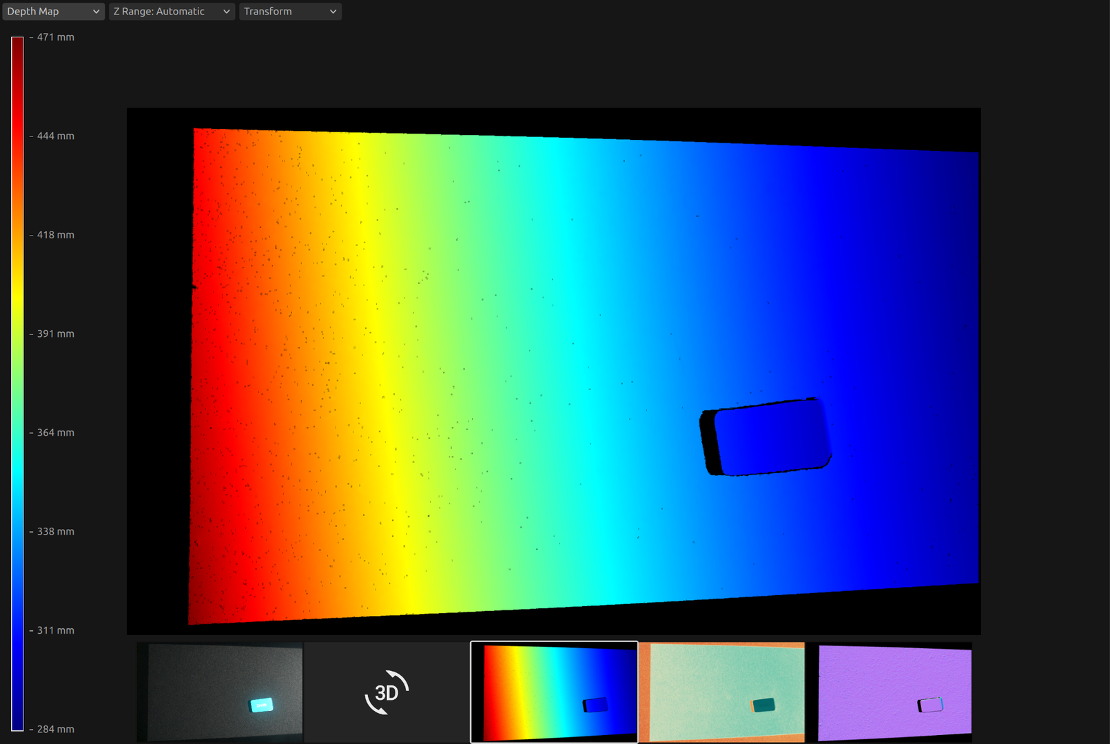
この時点で、マシンビジョンソフトウェアがワークピースを検出し、ピッキングポイントを推定する必要があります。この例では、ピッキングポイントが既知であり、カメラ参照フレーム内の画像座標として定義されていると仮定します。
ロボットベース参照フレーム内のピッキングポイントは次のように計算されます。まず点群を取得します。
次に、点群からカメラ参照フレーム内のピッキングポイント(XYZ 座標)を取得します。
print("Transforming single point")

xyz = point_cloud.copy_data("xyz")

point_in_camera_frame = np.array(
    [
        xyz[image_coordinate_y, image_coordinate_x, 0],
        xyz[image_coordinate_y, image_coordinate_x, 1],
        xyz[image_coordinate_y, image_coordinate_x, 2],
        1,
    ]
)
print(f"Point coordinates in camera reference frame: {point_in_camera_frame[0:3]}")
最後に、ピッキングポイントをロボットベースの参照フレームに変換します。
ピッキングポイントのみを変換する代わりに、点群全体をロボットのベース参照フレームに変換できます。これにより、マシンビジョンソフトウェアが点群からロボットベース参照フレーム内のピッキングポイントを直接見つけることができます。
Eye-to-hand
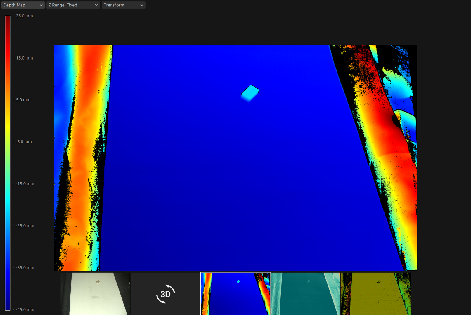
点群を ZDF 形式で取得するには、コードサンプルを実行するか、 サンプルデータ (ZividGemEyeToHandInRobotBaseFrame.zdf)の一部としてダウンロードします。
Eye-in-hand
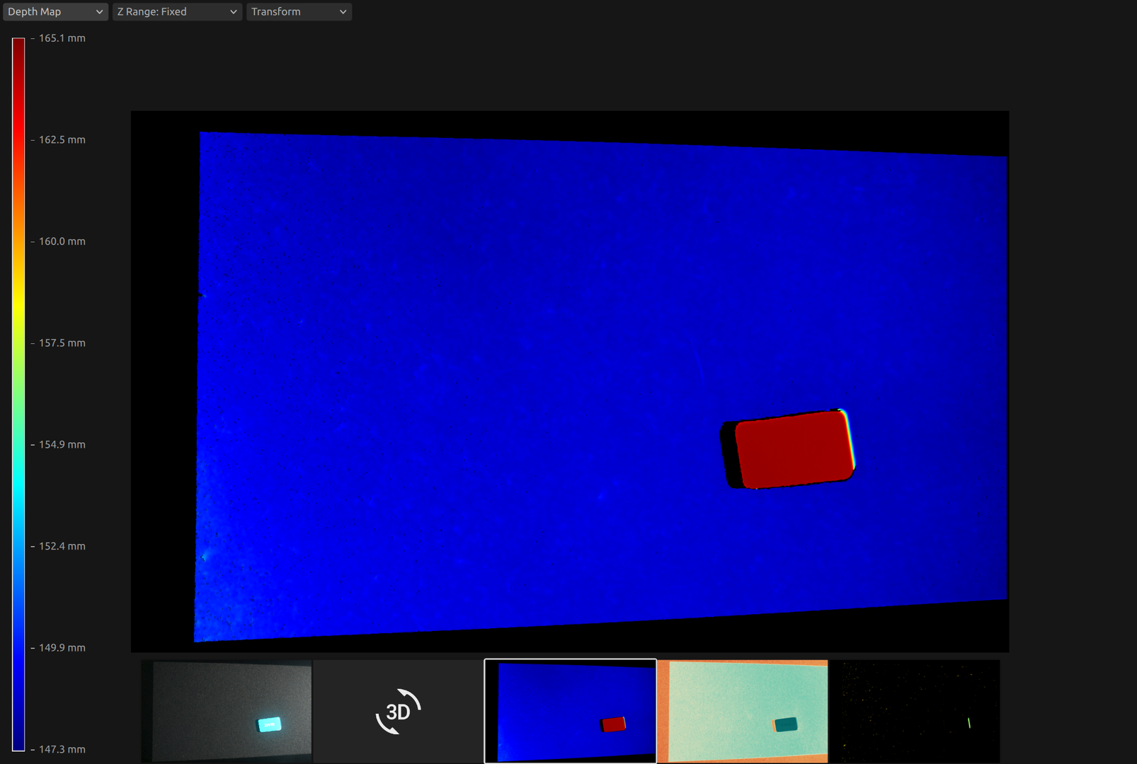
点群を ZDF 形式で取得するには、コードサンプルを実行するか、 サンプルデータ (ZividGemEyeInHandInRobotBaseFrame.zdf)の一部としてダウンロードします。
バージョン履歴
SDK |
変更点 |
|---|---|
2.12.0 |
ハンドアイキャリブレーションの結果を利用して、対象物の座標を Zivid カメラの座標系からロボットベースの座標系に変換する方法に関するセクションを追加しました。 |