Zivid キャリブレーションオブジェクト
Zivid は以下のキャリブレーションオブジェクトをサポートしています。
Zivid キャリブレーションボード
ArUco マーカー
Zivid Calibration Boards
The main Zivid calibration boards can be purchased at the Zivid WebShop. These boards are also used for camera maintenance with infield correction. To use the board in hand-eye calibration, both the checkerboard and ArUco marker need to be detectable in each capture.
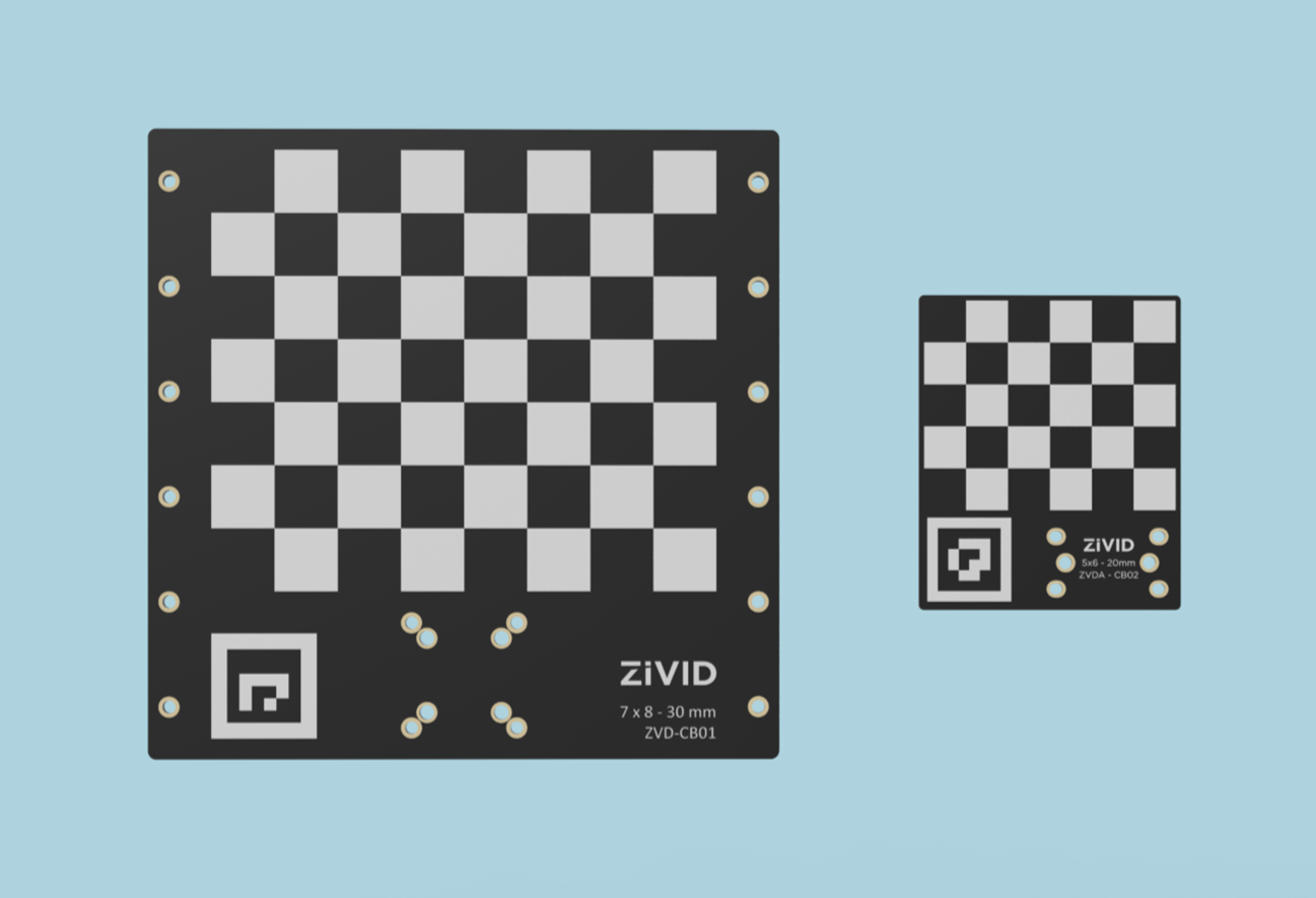
CAD files for the boards can be downloaded from CAD Downloads.
Pose Detection
The pose returned by the checkerboard detection has its origin at the top left inner corner of the checkerboard, with the axes oriented as shown below.
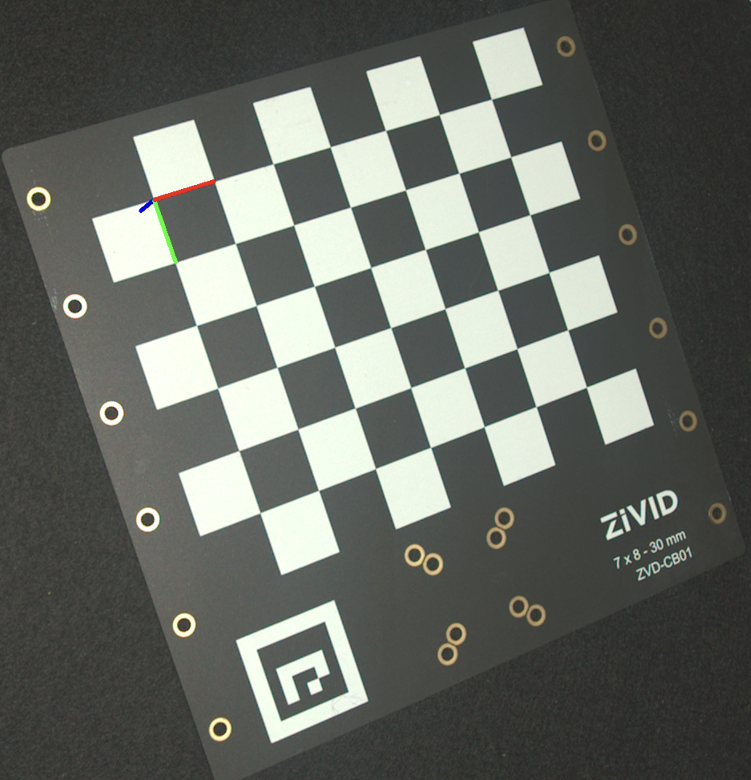
To estimate the pose, detect the checkerboard and read the pose from the detection result.

std::cout << "Detecting and estimating pose of the Zivid checkerboard in the camera frame" << std::endl;
const auto detectionResult = Zivid::Calibration::detectCalibrationBoard(frame);
if(!detectionResult.valid())
{
    throw std::runtime_error("No checkerboard detected. " + detectionResult.statusDescription());
}
const auto cameraToCheckerboardTransform = detectionResult.pose().toMatrix();
Console.WriteLine("Detecting and estimating pose of the Zivid checkerboard in the camera frame");
var detectionResult = Detector.DetectCalibrationBoard(frame);
var cameraToCheckerboardTransform = new Zivid.NET.Matrix4x4(detectionResult.Pose().ToMatrix());
print("Detecting and estimating pose of the Zivid checkerboard in the camera frame")
detection_result = zivid.calibration.detect_calibration_board(frame)

if not detection_result.valid():
    raise RuntimeError(f"No Checkerboard detected. {detection_result.status_description()}")

camera_to_checkerboard_transform = detection_result.pose().to_matrix()
The image above was created by projecting the pose onto the 2D image and drawing the coordinate system axes.
std::cout << "Converting to OpenCV image format" << std::endl;
const auto bgraImage = pointCloudToColorBGRA_SRGB(pointCloud);
std::cout << "Visualizing checkerboard with coordinate system" << std::endl;
cv::Mat bgrCoordinateSystem;
cv::cvtColor(bgraImage, bgrCoordinateSystem, cv::COLOR_BGRA2BGR);
drawCoordinateSystem(frame, cameraToCheckerboardTransform, bgrCoordinateSystem);
displayBGR(bgrCoordinateSystem, "Checkerboard transformation frame");
print("Converting to OpenCV image format")
bgra_image = point_cloud.copy_data("bgra_srgb")
print("Visualizing checkerboard with coordinate system")
bgr_coordinate_system = bgra_image[:, :, 0:3].copy()
_draw_coordinate_system(frame, camera_to_checkerboard_transform, bgr_coordinate_system)
display_bgr(bgr_coordinate_system, "Checkerboard transformation frame")
For the full example, see Transform via Checkerboard.
ArUco Markers
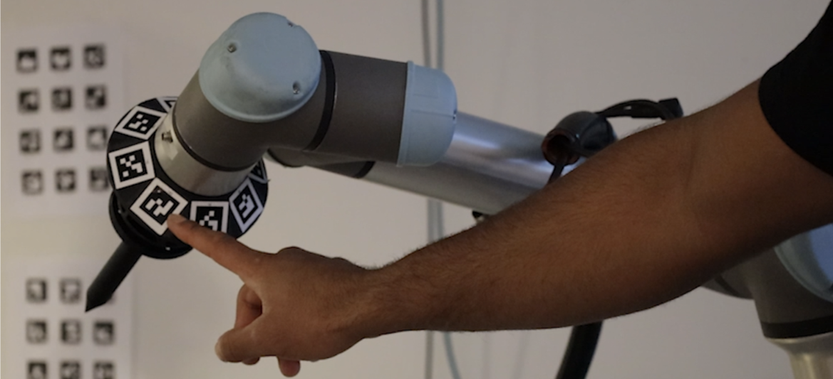
Zivid のハンドアイキャリブレーションは、1 つまたは複数の ArUco マーカーをキャリブレーションオブジェクトとして使用することもできます。一般的に、使用するマーカーの数が多いほど精度が向上します。ArUco マーカーは https://chev.me/arucogen/ で生成および印刷できます。マーカーは平らな面に印刷してください。サポートされている OpenCV 辞書は 4x4、5x5、6x6、および 7x7 です。ハンドアイキャリブレーションに ArUco マーカーを使用する利点の 1 つは、マーカーが小さいことです。もう 1 つは、すべてのマーカーが各キャプチャで検出可能である必要がないことです。

ArUco マーカーはどのくらいの大きさが必要ですか?
最も遠い撮像距離において、ArUco ビットの辺 1 辺あたり少なくとも 7 ピクセルを確保することをお勧めします。下の画像は、ArUco マーカーを拡大した画像で、各 ArUco ビットが 8 ピクセルで表現されています。必要な最小サイズ(mm 単位)の算出方法は、以下の例で説明します。
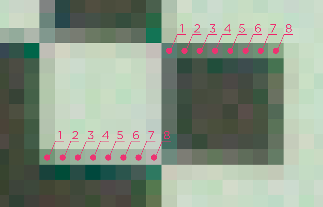
4x4 ArUco 辞書の場合、6 ビット(内側 4 ビットと外側 2 ビット)なので、マーカーの辺ごとに最低 42 ピクセルを目指してください。
Zivid 2+ M130 カメラを最大撮影距離 2 メートルで使用していると仮定します。このカメラと撮影距離における空間分解能は 0.5 mm です( FOV と撮像距離を計算する 参照)。0.5 mm に 42 ピクセルを掛けると 21 mm になります。
したがって、Zivid 2+ M130 を最大 2 メートルの距離で使用するには、ArUco マーカーのサイズが少なくとも 21 mm である必要があります。
注釈
ArUco マーカーの周囲には、少なくとも 1 ビットの余白を設けてください。上記の例では、各辺に 3.5 mm(7 ピクセル × 0.5 mm)の余白が必要です。
How should multiple ArUco markers be arranged?
When mounting several markers together on a custom target:
Arrange the markers in a genuine 2D pattern, such as a cross or grid, rather than a single line. Any 3 or more markers used for hand-eye calibration should span real 2D area, not sit on (or close to) one line.
Avoid placing mounting hardware, such as screws, brackets, clamps, or cables, where it can block the view of a marker from some viewing angles but not others. A marker that is consistently occluded across many poses can make the rotation residual large or invalid, even while translation residuals still look good.
See Unsatisfactory Hand-Eye Calibration Results (Multi-Marker ArUco Target: Good Translation, NaN or Extreme Rotation) for an example of what this looks like when it goes wrong.
Pose Detection
The pose returned by the ArUco marker detection has its origin at the center of the marker. Its z-axis points perpendicularly into the face of the marker, as shown below.
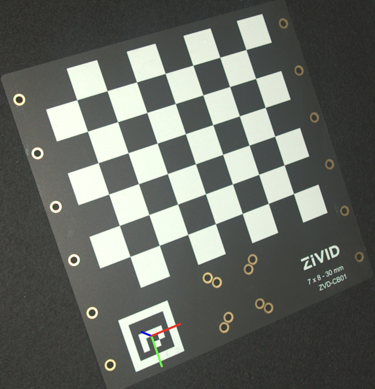
To estimate the pose, detect the marker and read the pose from the detected marker.
std::cout << "Detecting ArUco marker" << std::endl;
const auto detectionResult = Zivid::Calibration::detectMarkers(frame, markerId, markerDictionary);
std::cout << "Estimating pose of detected ArUco marker" << std::endl;
const auto cameraToMarkerTransform = detectionResult.detectedMarkers()[0].pose().toMatrix();
Console.WriteLine("Detecting ArUco marker");
var detectionResult = Detector.DetectMarkers(frame, markerId, markerDictionary);
Console.WriteLine("Estimating pose of detected ArUco marker");
var cameraToMarkerTransform = new Zivid.NET.Matrix4x4(detectionResult.DetectedMarkers()[0].Pose().ToMatrix());
The image above was created by projecting the pose onto the 2D image and drawing the coordinate system axes.
std::cout << "Converting to OpenCV image format" << std::endl;
const auto bgraImage = pointCloudToColorBGRA_SRGB(pointCloud);
std::cout << "Visualizing ArUco marker with coordinate system" << std::endl;
cv::Mat bgrCoordinateSystem;
cv::cvtColor(bgraImage, bgrCoordinateSystem, cv::COLOR_BGRA2BGR);
drawCoordinateSystem(frame, cameraToMarkerTransform, bgrCoordinateSystem);
displayBGR(bgrCoordinateSystem, "ArUco marker transformation frame");
print("Converting to OpenCV image format")
bgra_image = point_cloud.copy_data("bgra_srgb")
print("Visualizing ArUco marker with coordinate system")
bgr_coordinate_system = bgra_image[:, :, 0:3].copy()
_draw_coordinate_system(frame, camera_to_marker_transform, bgr_coordinate_system)
display_bgr(bgr_coordinate_system, "ArUco marker transformation frame")
For the full example, see Transform via ArUco marker.
どのキャリブレーションオブジェクトを使用すべきか?
可能な限り Zivid キャリブレーションボードの使用をお勧めします。以下の表に示すように、使用するカメラモデルに基づいてボードモデルを選択してください。
カメラモデル |
推奨ボード |
|---|---|
Zivid 2 M70 |
7x8 - 30 mm |
Zivid 2 L100 |
7x8 - 30 mm |
Zivid 2+ MR130 |
7x8 - 30 mm |
Zivid 2+ LR110 |
7x8 - 30 mm |
Zivid 2+ MR60 |
5x6 - 20 mm |
Zivid 3 XL250 |
7x8 - 30 mm |
ArUco マーカーは、以下の用途に使用してください。
Eye-to-hand 構成
キャリブレーションオブジェクトをロボットに恒久的に取り付ける必要がある場合
Zivid キャリブレーションボードが大きすぎる場合
キャリブレーションオブジェクトを選択したら、 Zivid ハンドアイキャリブレーションの実行と統合方法 を確認してください。
バージョン履歴
SDK |
変更点 |
|---|---|
2.18.0 |
Improved ArUco marker detection. |
2.16.0 |
より小型のキャリブレーションボード ZVDA-CB02 (5x6 20 mm) のサポートを追加しました。 |
2.14.0 |
9x6 のグレーと白のチェッカーボードのサポートを削除しました。 |
2.13.0 |
ArUco マーカーのサポートを追加しました。 |