Zivid Calibration Object
Zivid는 다음과 같은 보정 객체를 지원합니다.
Zivid Calibration Boards
ArUco Markers
The main Zivid calibration boards can be purchased at the Zivid WebShop. These boards are also used for camera maintenance with infield correction. To use the board in hand-eye calibration, both the checkerboard and ArUco marker need to be detectable in each capture.
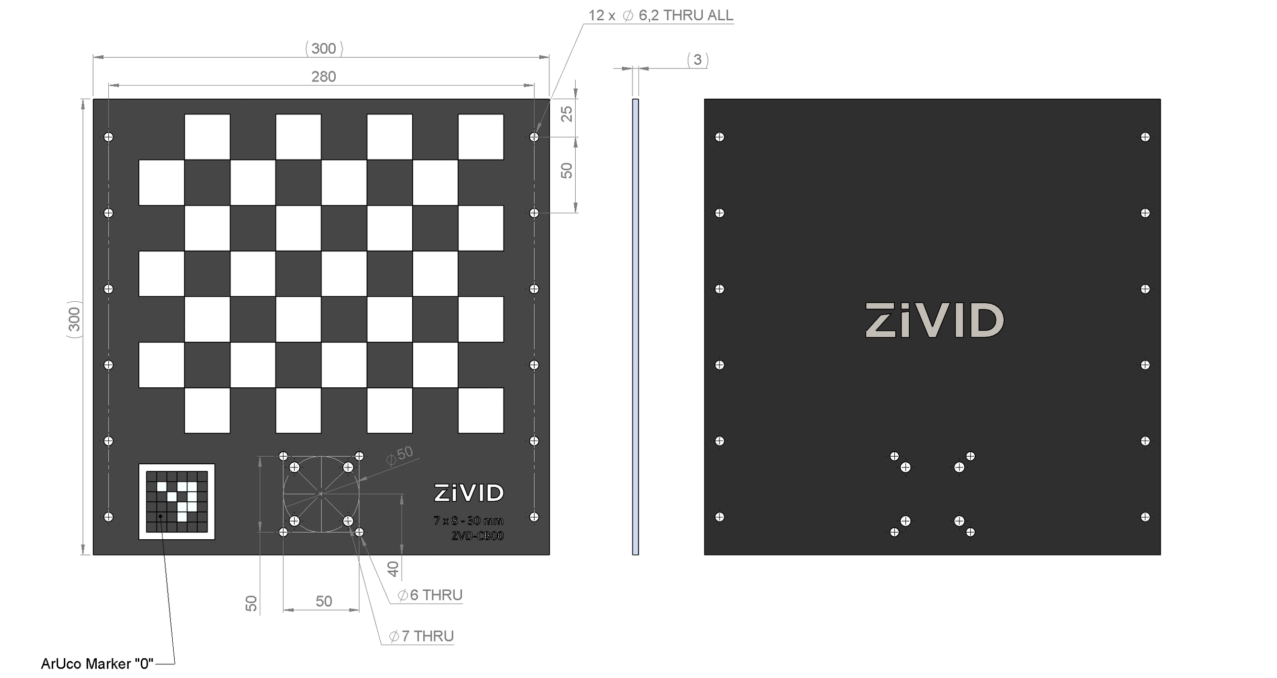
CAD files for the boards can be downloaded from CAD Downloads.
Pose Detection
The pose returned by the checkerboard detection has its origin at the top left inner corner of the checkerboard, with the axes oriented as shown below.
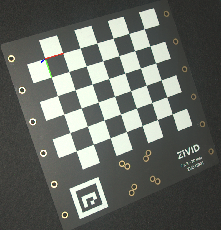
To estimate the pose, detect the checkerboard and read the pose from the detection result.

std::cout << "Detecting and estimating pose of the Zivid checkerboard in the camera frame" << std::endl;
const auto detectionResult = Zivid::Calibration::detectCalibrationBoard(frame);
if(!detectionResult.valid())
{
    throw std::runtime_error("No checkerboard detected. " + detectionResult.statusDescription());
}
const auto cameraToCheckerboardTransform = detectionResult.pose().toMatrix();
Console.WriteLine("Detecting and estimating pose of the Zivid checkerboard in the camera frame");
var detectionResult = Detector.DetectCalibrationBoard(frame);
var cameraToCheckerboardTransform = new Zivid.NET.Matrix4x4(detectionResult.Pose().ToMatrix());
print("Detecting and estimating pose of the Zivid checkerboard in the camera frame")
detection_result = zivid.calibration.detect_calibration_board(frame)

if not detection_result.valid():
    raise RuntimeError(f"No Checkerboard detected. {detection_result.status_description()}")

camera_to_checkerboard_transform = detection_result.pose().to_matrix()
The image above was created by projecting the pose onto the 2D image and drawing the coordinate system axes.
std::cout << "Converting to OpenCV image format" << std::endl;
const auto bgraImage = pointCloudToColorBGRA_SRGB(pointCloud);
std::cout << "Visualizing checkerboard with coordinate system" << std::endl;
cv::Mat bgrCoordinateSystem;
cv::cvtColor(bgraImage, bgrCoordinateSystem, cv::COLOR_BGRA2BGR);
drawCoordinateSystem(frame, cameraToCheckerboardTransform, bgrCoordinateSystem);
displayBGR(bgrCoordinateSystem, "Checkerboard transformation frame");
print("Converting to OpenCV image format")
bgra_image = point_cloud.copy_data("bgra_srgb")
print("Visualizing checkerboard with coordinate system")
bgr_coordinate_system = bgra_image[:, :, 0:3].copy()
_draw_coordinate_system(frame, camera_to_checkerboard_transform, bgr_coordinate_system)
display_bgr(bgr_coordinate_system, "Checkerboard transformation frame")
For the full example, see Transform via Checkerboard.
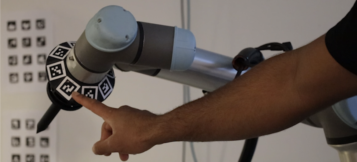
Zivid 핸드-아이 칼리브레이션은 하나 이상의 ArUco 마커를 보정 객체로 사용할 수도 있습니다. 일반적으로 마커를 많이 사용할수록 좋습니다. https://chev.me/arucogen/ 에서 ArUco 마커를 생성하고 인쇄할 수 있습니다. 마커는 평평한 표면에 인쇄해야 합니다. 지원하는 OpenCV 사전은 4x4, 5x5, 6x6, 7x7입니다. 핸드-아이 칼리브레이션에 ArUco 마커를 사용하는 한 가지 장점은 크기가 작다는 것입니다. 또 다른 장점은 각 캡처에서 모든 마커를 감지할 필요가 없다는 것입니다.

Pose Detection
The pose returned by the ArUco marker detection has its origin at the center of the marker. Its z-axis points perpendicularly into the face of the marker, as shown below.
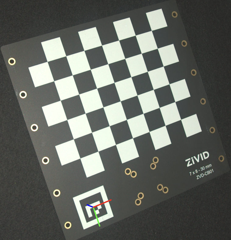
To estimate the pose, detect the marker and read the pose from the detected marker.
std::cout << "Detecting ArUco marker" << std::endl;
const auto detectionResult = Zivid::Calibration::detectMarkers(frame, markerId, markerDictionary);
std::cout << "Estimating pose of detected ArUco marker" << std::endl;
const auto cameraToMarkerTransform = detectionResult.detectedMarkers()[0].pose().toMatrix();
Console.WriteLine("Detecting ArUco marker");
var detectionResult = Detector.DetectMarkers(frame, markerId, markerDictionary);
Console.WriteLine("Estimating pose of detected ArUco marker");
var cameraToMarkerTransform = new Zivid.NET.Matrix4x4(detectionResult.DetectedMarkers()[0].Pose().ToMatrix());
The image above was created by projecting the pose onto the 2D image and drawing the coordinate system axes.
std::cout << "Converting to OpenCV image format" << std::endl;
const auto bgraImage = pointCloudToColorBGRA_SRGB(pointCloud);
std::cout << "Visualizing ArUco marker with coordinate system" << std::endl;
cv::Mat bgrCoordinateSystem;
cv::cvtColor(bgraImage, bgrCoordinateSystem, cv::COLOR_BGRA2BGR);
drawCoordinateSystem(frame, cameraToMarkerTransform, bgrCoordinateSystem);
displayBGR(bgrCoordinateSystem, "ArUco marker transformation frame");
print("Converting to OpenCV image format")
bgra_image = point_cloud.copy_data("bgra_srgb")
print("Visualizing ArUco marker with coordinate system")
bgr_coordinate_system = bgra_image[:, :, 0:3].copy()
_draw_coordinate_system(frame, camera_to_marker_transform, bgr_coordinate_system)
display_bgr(bgr_coordinate_system, "ArUco marker transformation frame")
For the full example, see Transform via ArUco marker.
ArUco 마커는 얼마나 커야 합니까?
가장 먼 이미징 거리에서는 ArUco 비트 측면당 최소 7개의 픽셀을 사용하는 것이 좋습니다. 아래 이미지는 각 ArUco 비트가 8개의 픽셀로 표현된 ArUco 마커의 확대된 이미지를 보여줍니다. 필요한 최소 크기를 mm 단위로 계산하는 방법은 다음 예시에서 설명합니다.
4x4 ArUco 사전의 경우 비트가 6개(내부 비트 4개, 외부 비트 2개)이므로 마커 측면당 최소 42픽셀을 목표로 해야 합니다.
Zivid 2+ M130 카메라를 최대 2m 거리에서 사용한다고 가정해 보겠습니다. 이 카메라와 거리의 공간 해상도는 0.5mm입니다( Calculate FOV and Imaging Distance 참조). 0.5mm에 42픽셀을 곱하면 21mm가 됩니다.
따라서 Zivid 2+ M130을 최대 2m 거리에서 사용하려면 ArUco 마커의 크기가 최소 21mm 이상이어야 합니다.
참고
ArUco 마커 주변에 최소 1비트의 여백을 남겨야 합니다. 위 예시의 경우, 각 변에 3.5mm(7픽셀 x 0.5mm)의 여백이 필요합니다.
Which Calibration Object to use?
We recommend using the Zivid calibration board whenever possible. Choose the board model based on the camera model you are using, as shown in the table below:
Camera Model |
Recommended Board |
|---|---|
Zivid 2 M70 |
7x8 - 30mm |
Zivid 2 L100 |
7x8 - 30mm |
Zivid 2+ MR130 |
7x8 - 30mm |
Zivid 2+ LR110 |
7x8 - 30mm |
Zivid 2+ MR60 |
5x6 - 20 mm |
Zivid 3 XL250 |
7x8 - 30mm |
Use ArUco markers for the following use case:
Eye-to-hand configuration
Calibration object needs to be permanently mounted on the robot
Zivid calibration board is too large
Now that you have selected the calibration object, check How to run and integrate Zivid Hand-Eye Calibration.
Version History
SDK |
Changes |
|---|---|
2.18.0 |
Improved ArUco marker detection. |
2.16.0 |
더 작은 칼리브레이션 보드 ZVDA-CB02 (5x6 20 mm) 에 대한 지원이 추가되었습니다. |
2.14.0 |
9x6 회색-흰색 체커보드에 대한 지원이 제거되었습니다. |
2.13.0 |
ArUco 마커에 대한 지원이 추가되었습니다. |