如何使用手眼标定的结果
我们分析了配备Zivid相机和机器视觉软件的机器人拾取物体的应用的要求。可参考 手眼标定的问题。如果您不确定应该如何使用手眼标定的结果,那么您可以在本篇教程中查看到相关信息。我们将介绍如何将对象的坐标从 Zivid 相机坐标系转换到机器人基坐标系。
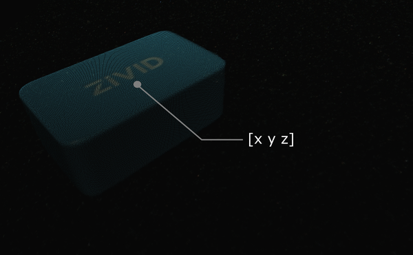
假设您通过机器视觉软件处理Zivid点云数据,相机检测到目标对象(例如此Zivid测试块),并估计其位置。给出的拾取点的x、y、z的值是对象基于Zivid相机坐标系的坐标值。
小技巧
在运行您的应用之前,建议您使用与手眼标定时相同的捕获周期来 预热 相机。如需进一步降低与温度相关的性能因素的影响,请启用 Thermal Stabilization(热稳定功能)。
在某些情况下,您的算法还需要输出对象的方向,例如翻转角(roll),俯仰角(pitch)和偏航角(yaw)。 这些参数也是基于Zivid相机的坐标系给出的。
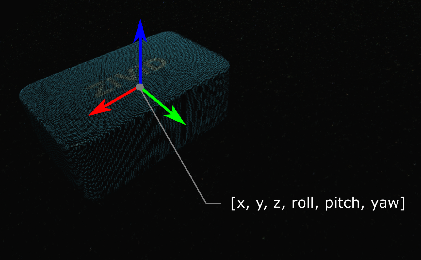
可通过齐次变换矩阵来描述对象的位姿(位置和方向)。 如果您还不熟悉(机器人)位姿和坐标系,请查看 位置、方向和坐标变换。
在实践中,最简单的方法是将点云从相机转换到机器人基坐标系。 Zivid SDK 支持在将数据复制到 CPU 之前对其进行 转换 ,因此速度非常快。
接下来我们将说明将单个点或整个点云从相机坐标转换到机器人基坐标的数学理论。下面有一个代码教程,演示如何将其付诸实践。
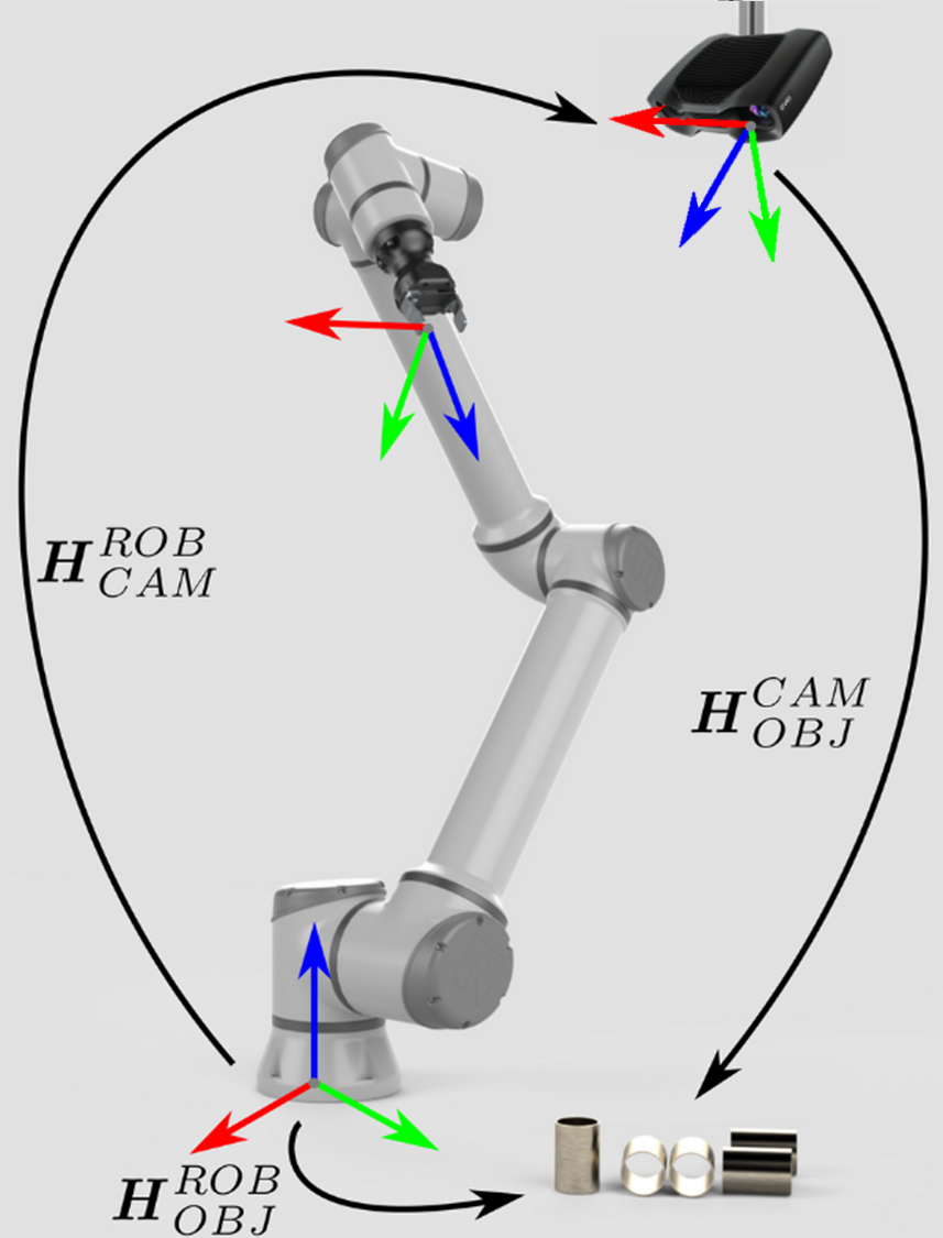
对于eye-to-hand系统,可以通过以下方法将单个3D点从Zivid相机坐标系转换到机器人基坐标系:
如果要将整个Zivid点云从相机坐标系转换到机器人基坐标系,请将上述方程式应用于点云中的每个点。
另一方面,如果要将对象的位姿转换为相对于Zivid相机坐标系的位姿,请应用以下方程式:
请确保位姿是通过齐次变换矩阵表述的。 如果不是,请查看我们的文章 常见的姿态表示方法之间的转换。
由此产生的位姿是机器人工具中心点 (TCP) 应该达到的位姿以进行拾取。 TCP 和机器人法兰之间的偏移量应在机器人侧考虑。
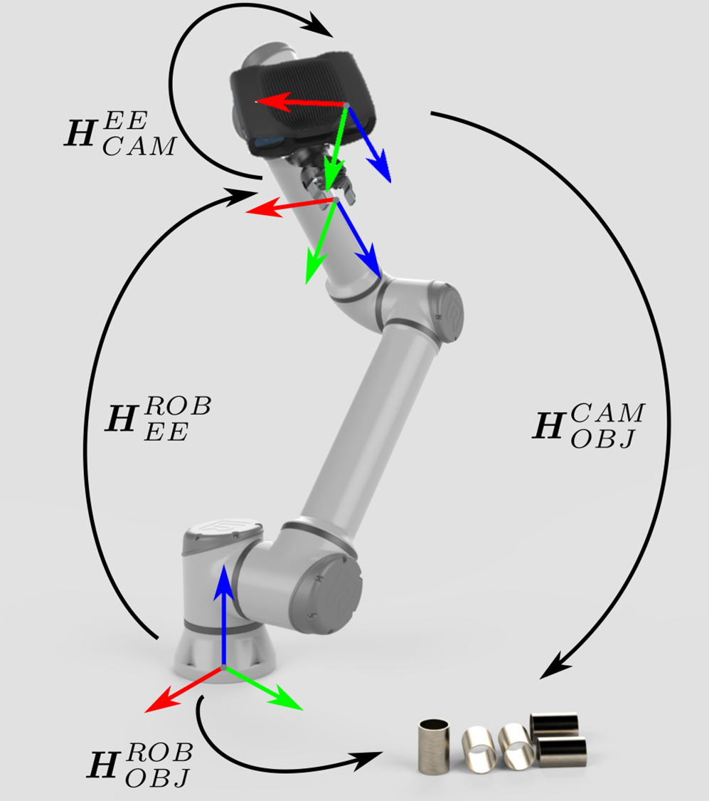
Eye-in-hand系统的方法是类似的。不同之处在于方程式必须包含机器人的当前位姿。同样地,我们假定机器人位姿用齐次变换矩阵表示。如果您的机器人位姿表示方式有所不同,请查看我们关于 常见的姿态表示方法之间的转换 的文章。
以下方程式描述了如何将单个3D点从Zivid相机坐标系转换到机器人基坐标系:
如果要将整个Zivid点云从相机坐标系转换到机器人基坐标系,请将上述方程式应用于点云中的每个点。
要将对象的位姿转换为相对于Zivid相机坐标系的位姿,请使用以下方程式:
由此产生的位姿是机器人工具中心点 (TCP) 应该达到的位姿以进行拾取。 TCP 和机器人法兰之间的偏移量应在机器人侧考虑。
为了将这一理论付诸实践,让我们按照教程将单个点或整个点云从相机转换到机器人基坐标系。
"""
Transform single data point or entire point cloud from camera to robot base reference frame using Hand-Eye calibration
matrix.

This example shows how to utilize the result of Hand-Eye calibration to transform either (picking) point coordinates
or the entire point cloud from the camera to the robot base reference frame.

For both Eye-To-Hand and Eye-In-Hand, there is a Zivid gem placed approx. 500 mm away from the robot base (see below).
The (picking) point is the Zivid gem centroid, defined as image coordinates in the camera reference frame and hard-coded
in this code example. Open the ZDF files in Zivid Studio to inspect the gem's 2D and corresponding 3D coordinates.

Eye-To-Hand
- ZDF file: ZividGemEyeToHand.zdf
- 2D image coordinates: (1035,255)
- Corresponding 3D coordinates: (37.77 -145.92 1227.1)
- Corresponding 3D coordinates (robot base reference frame): (-12.4  514.37 -21.79)

Eye-In-Hand:
- ZDF file: ZividGemEyeInHand.zdf
- 2D image coordinates: (1460,755)
- Corresponding 3D coordinates (camera reference frame): (83.95  28.84 305.7)
- Corresponding 3D coordinates (robot base reference frame): (531.03  -5.44 164.6)

For verification, check that the Zivid gem centroid 3D coordinates are the same as above after the transformation.

The YAML files for this sample can be found under the main instructions for Zivid samples.

"""
首先,我们获得机器人基础参考系中的相机位姿(眼手标定的结果)。
点云在相机参考系中给出。
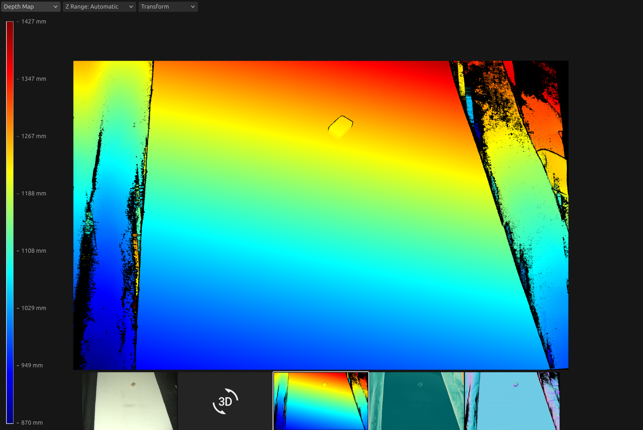
此时,您的机器视觉软件应该检测工件并估计拾取点。在示例中,我们假设拾取点已知,定义为相机参考系中的图像坐标。
然后按如下方式计算机器人基础参考系中的拾取点。我们首先得到点云。
首先,我们得到以下位姿:
法兰(末端执行器)参考系中的相机位姿(手眼标定结果)
机器人基础参考系中的法兰(末端执行器)位姿(当前机器人位姿)
eye_in_hand_transform_file_path = get_sample_data_path() / "EyeInHandTransform.yaml"
robot_transform_file_path = get_sample_data_path() / "RobotTransform.yaml"

print("Reading camera pose in flange (end-effector) reference frame (result of eye-in-hand calibration)")
flange_to_camera_transform = load_and_assert_affine_matrix(eye_in_hand_transform_file_path)

print("Reading flange (end-effector) pose in robot base reference frame")
base_to_flange_transform = load_and_assert_affine_matrix(robot_transform_file_path)
通过将这两个变换矩阵相乘,我们得到机器人基础参考系中的相机位姿。
点云在相机参考系中给出。
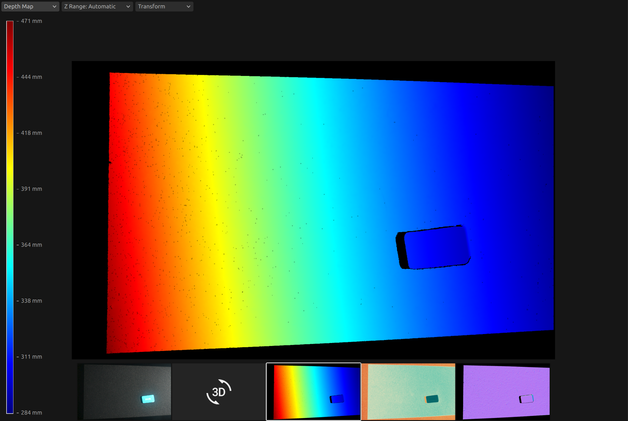
此时,您的机器视觉软件应该检测工件并估计拾取点。在示例中,我们假设拾取点已知,定义为相机参考系中的图像坐标。
然后按如下方式计算机器人基础参考系中的拾取点。我们首先得到点云。
然后,从点云中,我们得到相机参考系中的拾取点(XYZ坐标)。
print("Transforming single point")

xyz = point_cloud.copy_data("xyz")

point_in_camera_frame = np.array(
    [
        xyz[image_coordinate_y, image_coordinate_x, 0],
        xyz[image_coordinate_y, image_coordinate_x, 1],
        xyz[image_coordinate_y, image_coordinate_x, 2],
        1,
    ]
)
print(f"Point coordinates in camera reference frame: {point_in_camera_frame[0:3]}")
最后,我们将拾取点变换到机器人基础参考系。
我们可以将整个点云转换到机器人基础参考系,而不是仅变换拾取点。这使您的机器视觉软件能够直接从点云中找到机器人基础参考系中的拾取点。
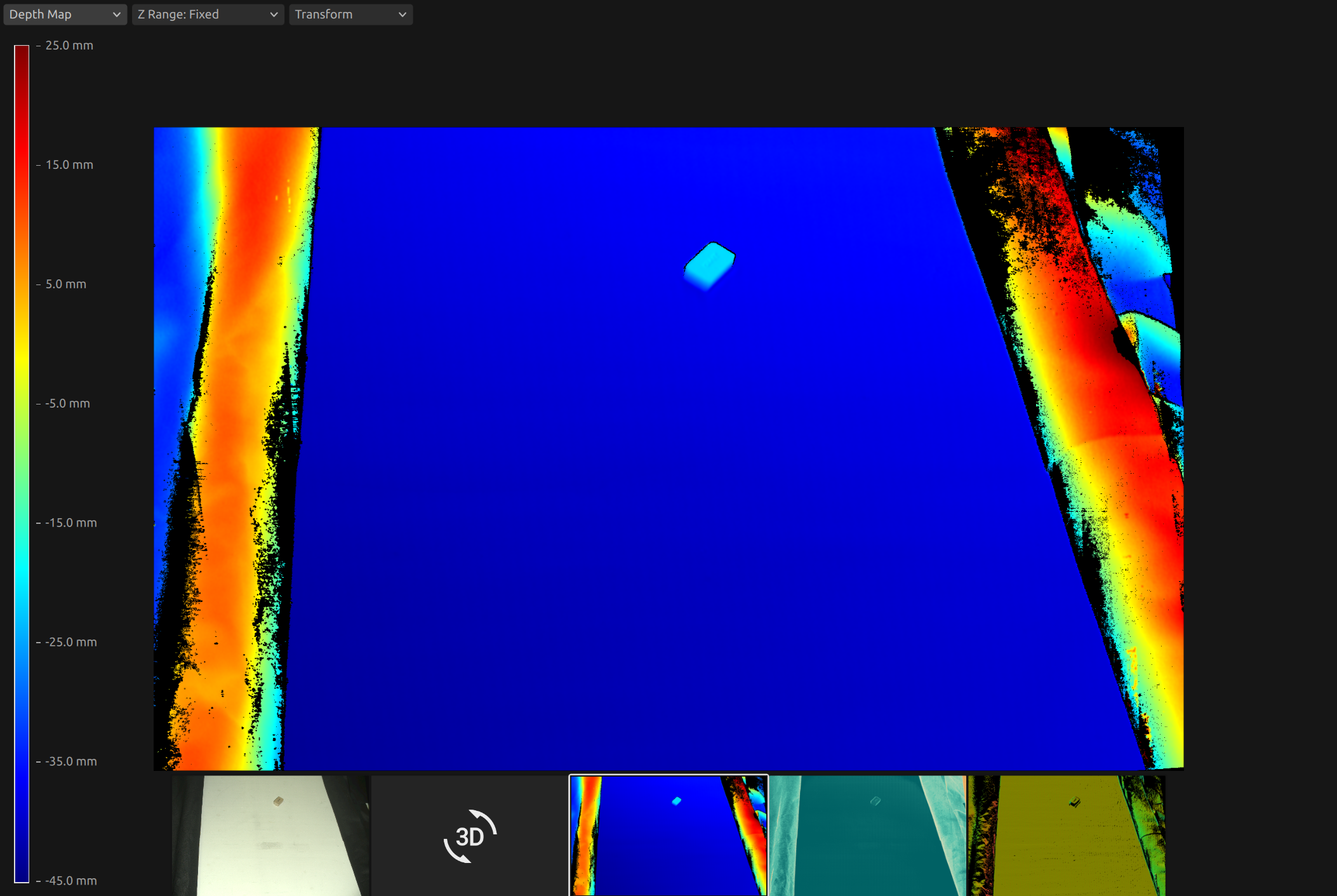
如需获取 ZDF 格式的点云,您可以运行代码示例或将其作为 示例数据 (ZividGemEyeToHandInRobotBaseFrame.zdf) 的一部分下载。
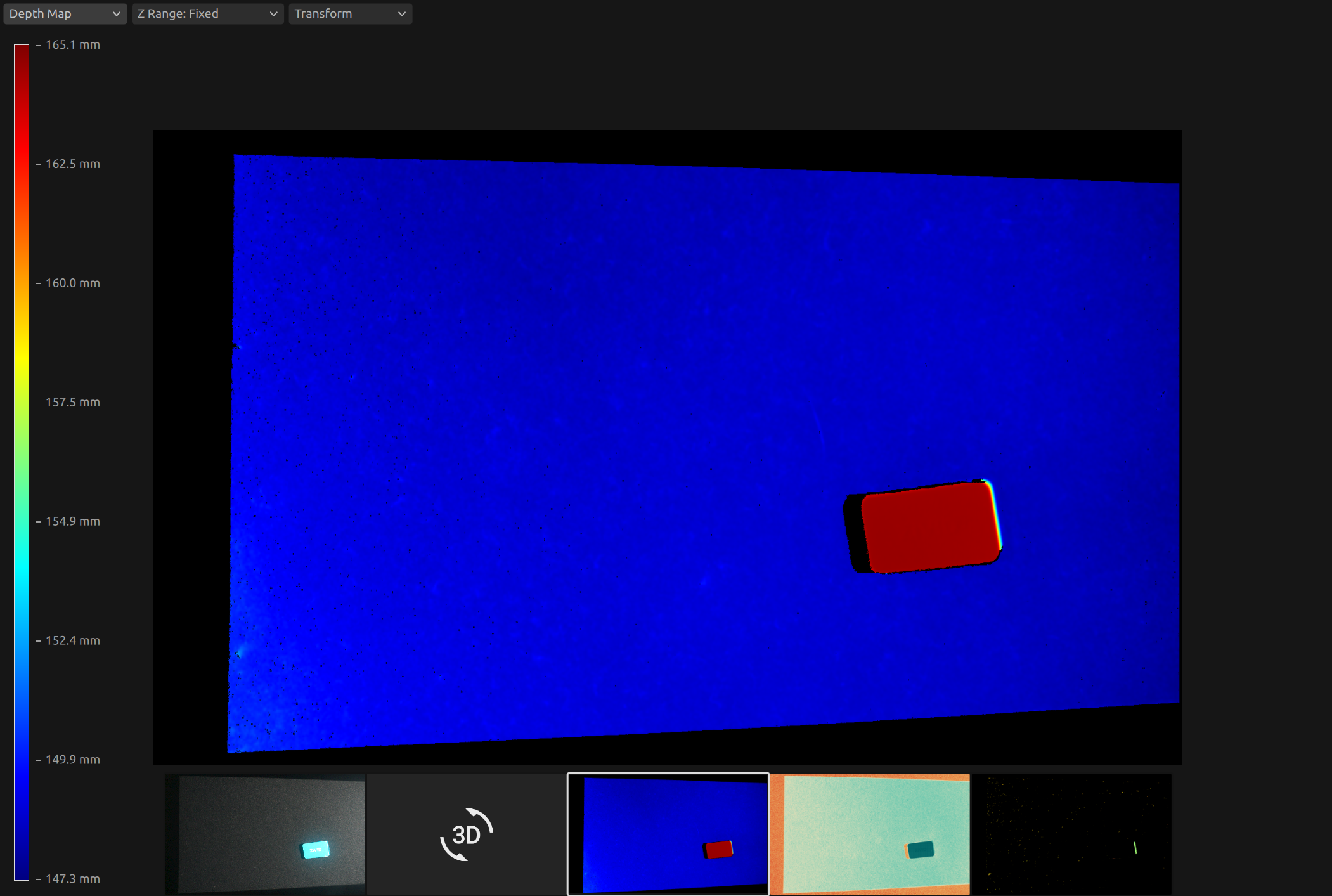
如需获取 ZDF 格式的点云,您可以运行代码示例或将其作为 示例数据 (ZividGemEyeInHandInRobotBaseFrame.zdf) 的一部分下载。
版本历史
SDK |
变更 |
|---|---|
2.12.0 |
新增了关于如何利用手眼标定的结果将对象的坐标从 Zivid 相机坐标系转换到机器人基坐标系的内容。 |
