Hand-Eye GUI
Introduction
This guide walks you through the Zivid Hand-Eye GUI, from setup to calibration and verification, using the Python samples and RoboDK.
Prerequisites and Setup
Zivid Python installed
[Optional] RoboDK installed and configured with robot poses/targets/safe points. See Create poses for HE calibration in RoboDK
Hardware setup:
Zivid camera connected to the PC
[Optional] Robot with digital twin in the RoboDK robot library
[Optional] Robot connected to the PC
Initialization
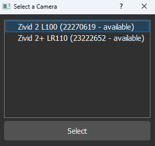
Select a camera: Choose one of the connected cameras. If a firmware upgrade is required, you will be prompted in the next step.
2. Select a camera setting: Choose the settings that will be used for the Hand-Eye calibration. We recommend using the same settings as your final application.
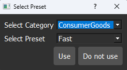
If you prefer to load a predefined YAML settings file. Click “Do Not Use”, and a file browser will open so you can manually select a YAML file. If you refuse to load a file, you will be prompted to choose Vision Engine and Sampling (3D).
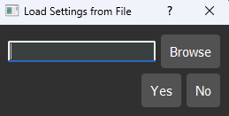
You can also load a settings file later from the GUI during normal use.
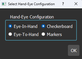
3. Select the setup type: Choose the Hand-Eye calibration type based on your system configurations and the Calibration Object you will use.
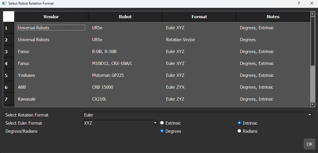
Select the rotation representation format: Choose the rotation format and unit that match your robot. You can either pick a robot from the list or manually configure the settings. The table below includes popular robots, but all formats are supported.
For more details on pose representations and how to convert between them, see: Pose Conversions
Note
It is possible to use the GUI even if RoboDK is not configured or if no robot is connected. However, in this case, only functionalities related to the camera will be available. Features that require a connected robot will be disabled until a robot is properly configured and connected.
Tip
After the initialization process, whenever you select a functionality in the GUI (e.g., WARMUP), a step-by-step checklist appears in the top-right section. This checklist outlines the exact sequence of actions to complete the task and must be followed in order.
Warmup
Ensure the camera is warmed up before calibration for optimal accuracy.
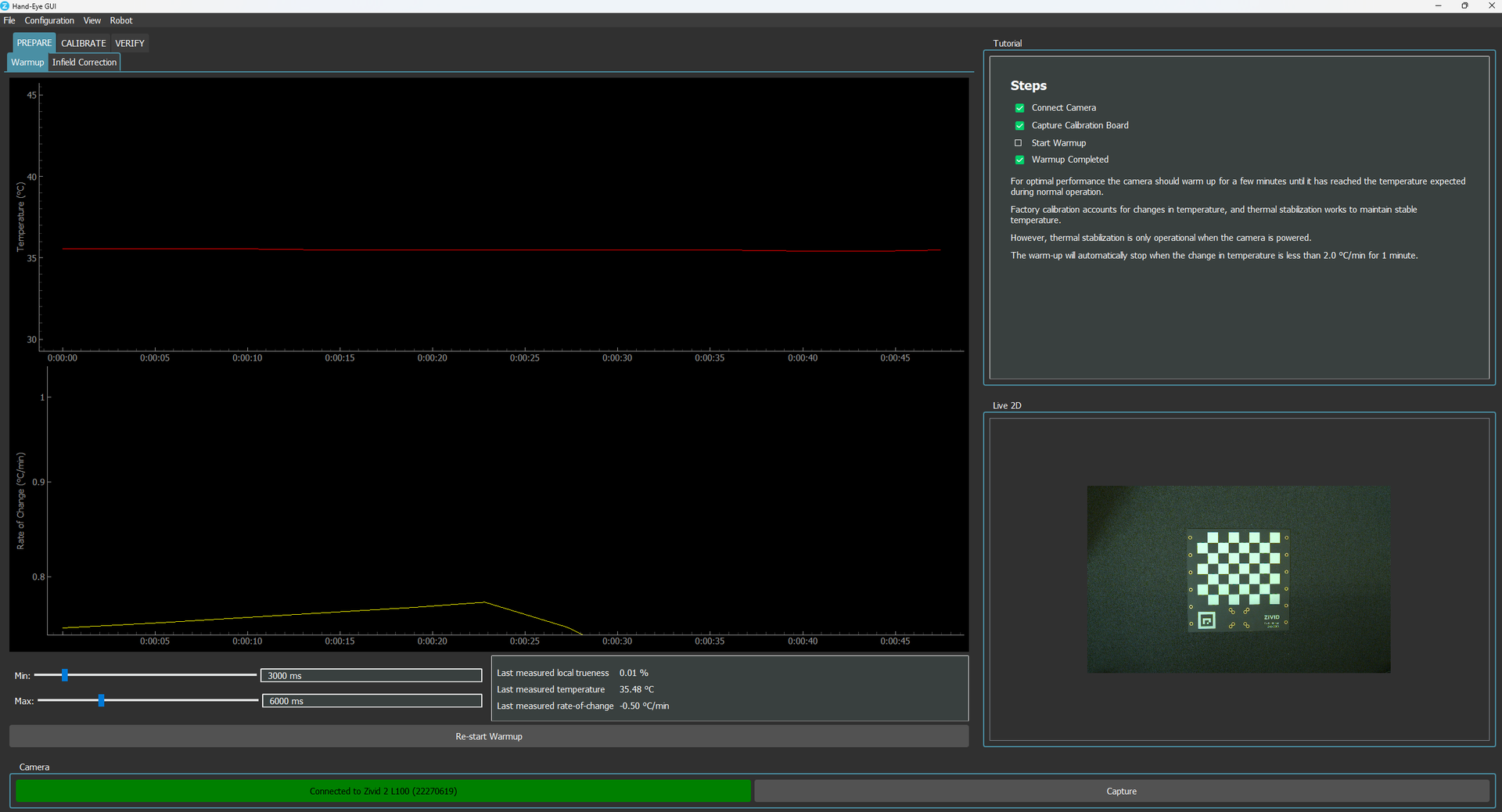
See: Camera warmup guide for more information.
Infield Correction
For best results, apply infield correction before hand-eye calibration.
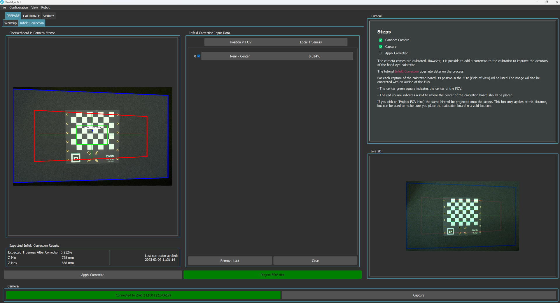
See: Infield Correction for more information.
Calibration
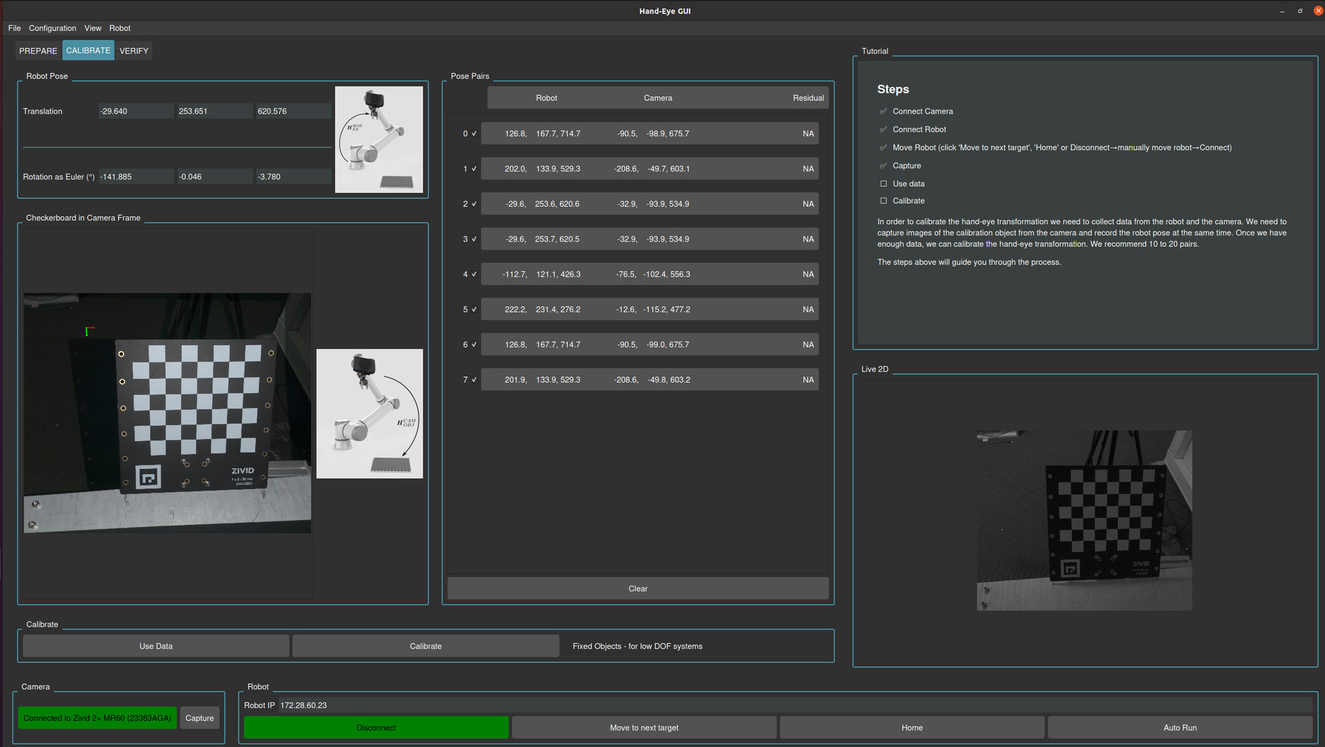
Run the Hand-Eye calibration procedure using the GUI by following the instructions in the Tutorial section (top right).

See: Hand-Eye Calibration Process for more information.
Verification
After performing Hand-Eye calibration, it’s essential to validate the accuracy of the transformation between the camera and robot coordinate systems. The GUI has several complementary methods to ensure the calibration is precise and reliable:
Verification by Touch Test
This method involves specifying the end-effector tool’s physical dimensions, including the tool tip offset. A Zivid camera captures the scene, and an ArUco marker (with known type and dictionary) is detected. Its 3D pose is estimated in the camera frame and transformed into the robot base frame using the Hand-Eye calibration. The robot then physically touches the marker’s center with the end-effector.
For tool specifications and detailed test instructions, see: Touch test procedure.
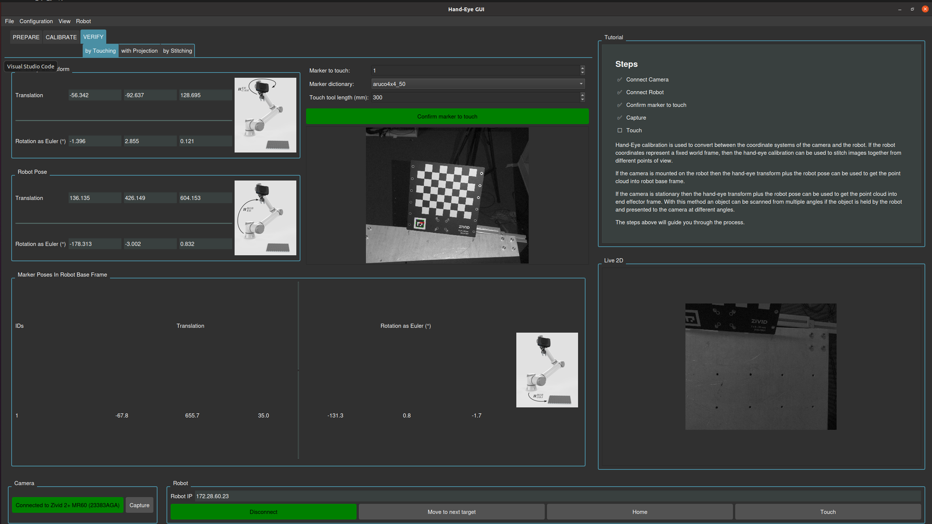
In the image below, you can see the expected result from the Verification by Touch Test.
Verification by Projection
The camera projects green circles onto the known checkerboard corners of the Zivid calibration board.
The test is initialized by instructing the system where the calibration object is located in the robot coordinate system. This is done through an initial capture, using the known pose of the robot and the Hand-Eye transformation matrix.
For each consecutive robot pose, the position of the calibration board in the camera coordinate system is calculated. This is computed using the:
robot pose
known location of the calibration object in the robot coordinate system
Hand-Eye transformation matrix
The calculated position of the calibration object is projected into the projector image plane, and subsequently projected back onto the physical scene using the projector.
For more details on the projection process, see: 2D Image Projection.
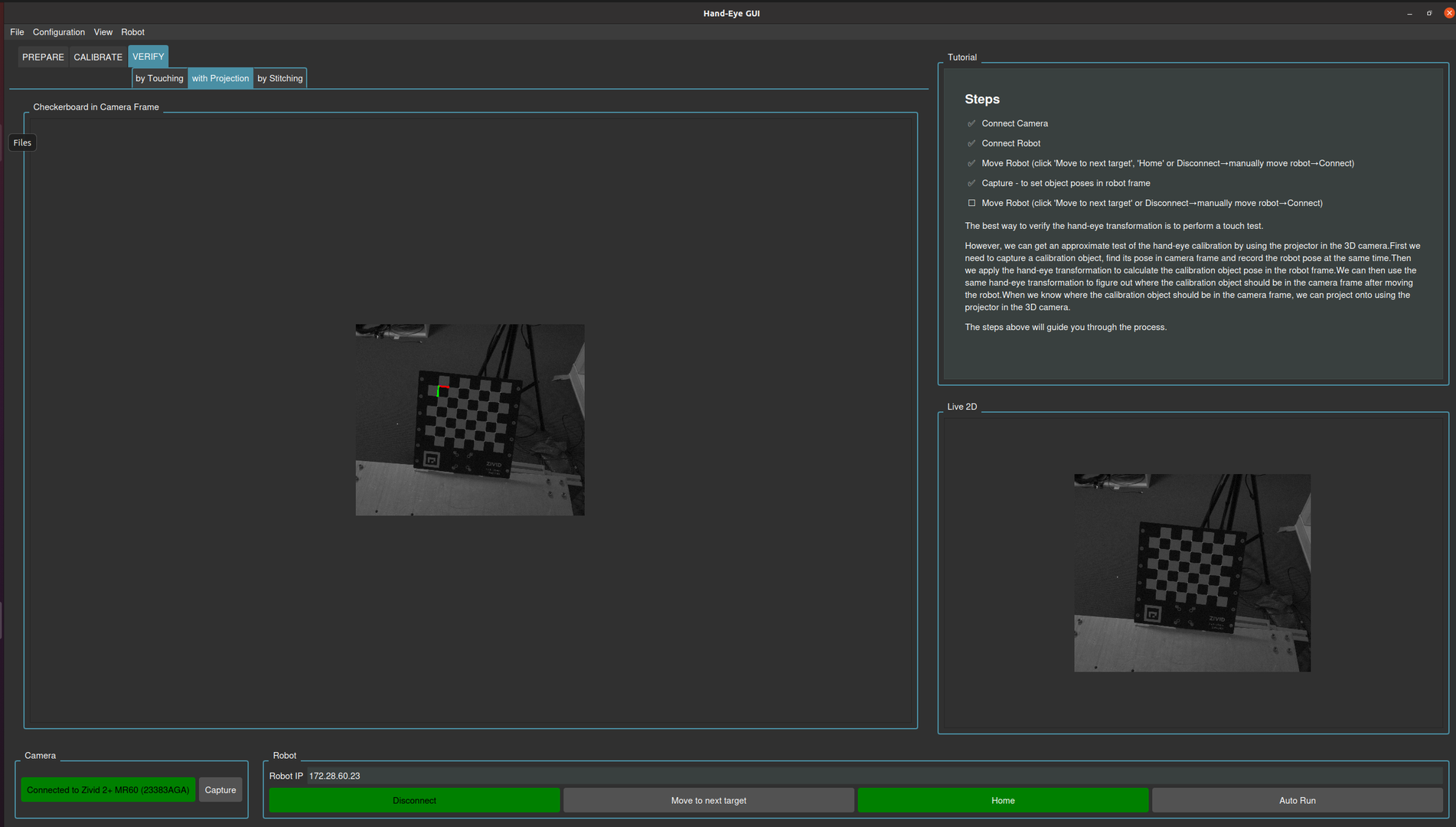
In the image below, you can see the expected result from the Verification by Projection.
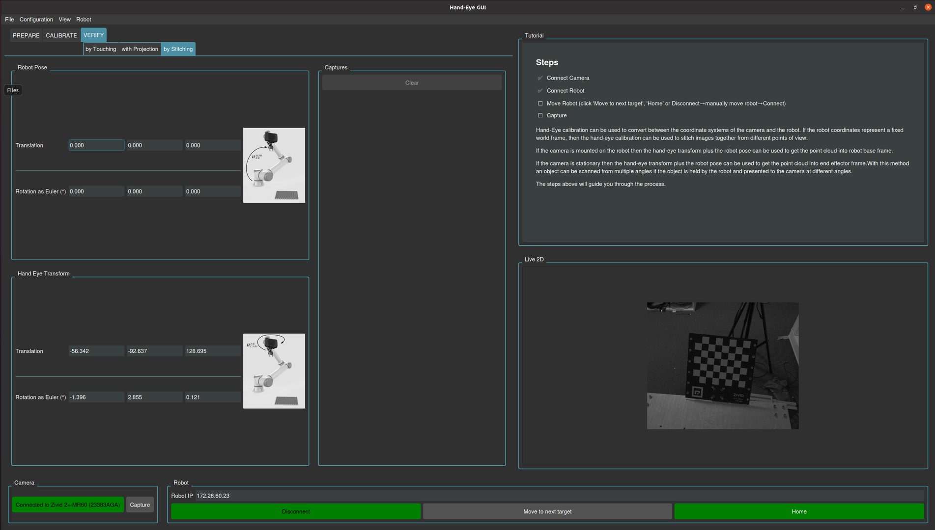
Verification by Stitching
For each robot pose, a 3D point cloud is captured with the Zivid camera and transformed into the robot base frame using the Hand-Eye transformation matrix. Repeating this across poses and merging the transformed clouds into a common frame creates a stitched scene. Accurate calibration yields a clean reconstruction with checkers accurately aligned, while poor calibration results in artifacts like offsets or misalignments between the checkers.
