Any Robot + RoboDK + Python: Generate Dataset and Perform Hand-Eye Calibration
Note
This tutorial has only been tested on UR5e and Yaskawa H10, and it only works with robots supported by RoboDK.
Introduction
Accurate hand-eye calibration requires a good dataset, but generating this dataset can be a difficult task. One way to simplify this task is to save the robot poses beforehand and automate the acquisition process afterward. In this tutorial, we use RoboDK to automate the acquisition of the hand-eye dataset. This provides us with the required 3D images and robot poses needed to get the hand-eye transform matrix from Zivid hand-eye calibration. This sample works for both eye-in-hand and eye-to-hand.
If you are not familiar with hand-eye calibration, we recommend going through the Hand-Eye Calibration article to get started.
Requirements
Zivid software installed, including Zivid Tools if on Linux.
Zivid-Python installed.
RoboDK software installed.
A robot that has a digital twin in the Robodk robot library.
Set Up RoboDK Environment
RoboDK .rdk files store information about the robot, target poses, and environment. The components in the .rdk file needed and useful to generate the hand-eye calibration dataset are:
Robot model file (.robot)
List of target poses (i.e., Target 0, Target 1, Target 2, etc.)
Virtual model of robot’s environment (optional)
CAD model of the camera the in use, e.g., Zivid 2 CAD file (optional)
Take a look by opening this .rdk file example in RoboDK. example file
Add Robot to RoboDK Environment
Start by opening the RoboDK program and adding the robot that will be used. To add the robot, open the library using the GUI by going to File -> Open online library. Find the robot that matches your model through this interface, hover over it with the mouse and choose Open. If the robot does not appear in the station, choose Download instead and drag and drop it into the .rdk environment. This is also described in the Select a robot RoboDK tutorial.
Connect to Robot through RoboDK
Warning
Depending on the brand of the robot being used, a driver setup might be required to connect to RoboDK. For help on this setup, check out the robot tips section in the RoboDK documentation. For example, here is the advice for ABB robots.
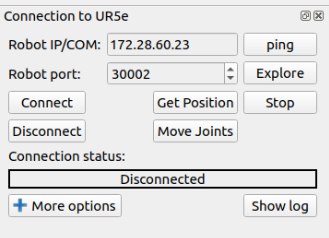
Before running the Hand-Eye script, it is first necessary to connect to the robot using the RoboDK interface. In RoboDK GUI navigate to Connect -> Connect Robot. This will open a side panel where you can insert the Robot IP and the port number.
Note
Most robots will have a remote mode on their control pendant or tablet. Make sure your robot is in remote mode to be able to establish the connection.
To connect to the robot you must know its IP address, it should be found/listed in the robot control pendant. Follow the steps for connecting to the robot for RoboDK. Another connection that should be verified is the port number. The default number that comes with the driver should work unless changes have been made previously.
Just click Connect and if the Connection status box is green, the RoboDK interface can be used to control the robot. If it is red instead, make sure that you have the right port number and IP address. If it is still red, check the Troubleshoot RoboDK chapter at the end of this tutorial.
Create Poses for Hand-Eye Calibration
Learn how to create a target in RoboDK in order to save the poses.
Creating poses using RoboDK can be approached in two ways:
Moving the robot physically to the desired poses using the pendant, then connecting through RoboDK to record the poses
Moving the robot remotely through RoboDK to create and save the poses
Tip
If you are moving the robot through RoboDK and the robot is not moving fast enough or slow enough, check this link to set the robot speed in RoboDK. After setting the speed, remember to right click on the program that you have created and mark Run on the robot and then right click again and choose Run.
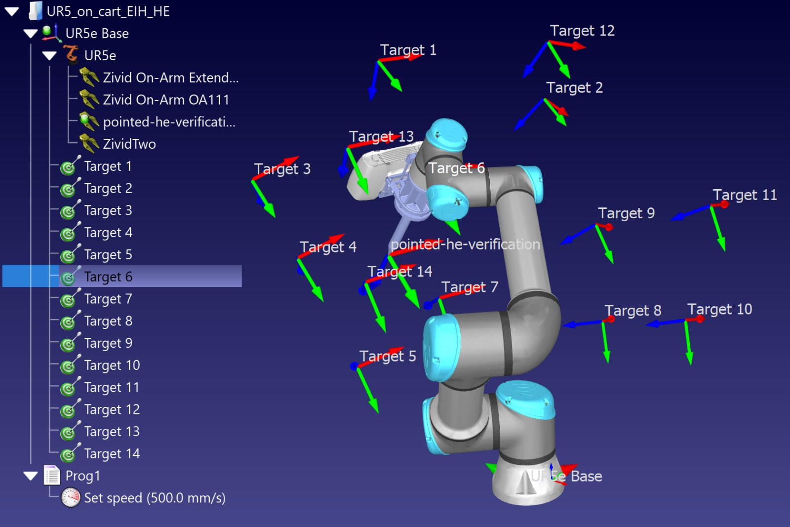
Each pose that is added to the sequence should have the camera facing the calibration object and keep the entire object in the field of view. The calibration object should be centered in the image. When creating the poses, use Zivid Studio to capture in live mode as you move the robot into position. This helps pick the orientations that will provide the best coverage. It is recommended to have between 10-20 poses to get an accurate hand-eye transform. You can see illustrated below how it looks in RoboDK.
Run the Python Script
Before running the script, it is required to have the .rdk file open and be connected to the robot. The script can be found in the Zivid python samples; it takes the following mandatory command line arguments shown below.
type_group.add_argument("--eih", "--eye-in-hand", action="store_true", help="eye-in-hand calibration")
type_group.add_argument("--eth", "--eye-to-hand", action="store_true", help="eye-to-hand calibration")
parser.add_argument(
    "--settings-path",
    required=False,
    type=Path,
    help="Path to the camera settings YML file",
)
parser.add_argument("--ip", required=True, help="IP address of the robot controller")
parser.add_argument(
    "--target-keyword",
    required=True,
    help='This is the keyword shared for naming all poses used for hand-eye dataset, i.e. if we have: "Target 1", "Target 2", ... , "Target N". Then we should use "Target"',
)
subparsers = parser.add_subparsers(dest="calibration_object", required=True, help="Calibration object type")
subparsers.add_parser("checkerboard", help="Use checkerboard for calibration")
marker_parser = subparsers.add_parser("marker", help="Use marker for calibration")
marker_parser.add_argument(
    "--dictionary",
    required=True,
    choices=list(zivid.calibration.MarkerDictionary.valid_values()),
    help="Dictionary used for marker calibration",
)
marker_parser.add_argument("--ids", nargs="+", required=True, type=int, help="IDs used for marker calibration")
Once the script is initialized, it will give the option to choose an alternative path for storing the dataset and results. If the path is not specified, the dataset and results will be stored in hand-eye/datasets/<date acquired>. The script runs through the given poses and performs a hand-eye calibration, as follows.
Script walk-through
For the RoboDK hand-eye calibration script to be functional it requires two additional Python files.
robodk_tools.py is used to configure the robot.
save_load_matrix.py is used to save and load matrices to or from YAML files.
The script runs through the following steps respectively:
Connect to robot
Firstly we need to connect to the robot using the function connect_to_robot() from robodk_tools.py by providing the IP address as an argument.
The function returns a rdk object that is used to establish a link with the simulator and a robot object that contains various robot configuration parameters.
Set robot targets
We then get a list of targets using the get_robot_targets() function from robodk_tools.py.
This list is obtained from the RoboDK .rdk file and contains the robot pose for each target.
To acquire the list of targets we need to provide as arguments the rdk object that we obtained in the previous step and the target keyword provided by the user.
Set robot speed and acceleration
The last step of the robot configuration is defining the speed and acceleration of the robot.
To define those parameters, we create a list of 4 integers named robot_speed_accel_limits: linear speed, joint speed, linear acceleration, and joint acceleration, respectively.
Then, using the set_robot_speed_and_acceleration() function from robodk_tools.py, with robot object and robot_speed_accel_limits as arguments, the robot configuration is done.
Generate Hand-Eye dataset
Now we generate the hand-eye dataset by moving the robot to each pose in the list of targets.
For each pose, we capture and save the ZDF file and the robot’s pose during capture.
In this step, the user is asked to provide the path to a directory where a folder named datasets/hand-eye will be created and the dataset will be saved to.
If the path is not provided, the default path will be used (location of this script).
To generate this dataset we use the generate_hand_eye_dataset() function.
It takes as arguments a zivid application, app object, to gain access to the camera, and a robot object to get the list of targets to move the robot to.
Perform Hand-Eye calibration
To perform the hand-eye calibration, we iterate over all robot poses and ZDF files saved from the previous step.
Using the perform_hand_eye_calibration() function with the type of calibration (eye-in-hand or eye-to-hand) and the path to the dataset directory as arguments, we obtain the hand-eye transformation matrix and residuals.
Save Hand-Eye results
Lastly, the transformation matrix and residuals are saved.
This is done by using the function save_hand_eye_results() with the path where to save it (in this case, in the dataset directory) as an argument.
Verify and use Transform from Hand-Eye
After completing hand-eye calibration, you may want to verify that the resulting transformation matrix is correct and within the accuracy requirements.
We have a sample to verify the hand-eye calibration with visualization, where all point clouds are transformed to the robot base, using the hand-eye calibration transform, and displayed overlapped. By visually checking how well the calibration object point clouds overlap, we can understand how accurate the robot poses and hand-eye transform are. In other words, we visualize our hand-eye calibration accuracy and robot positioning accuracy.
An alternative verification approach, which we recommend, is to place the Zivid Calibration Object in your scene and run our touch test sample. The sample will capture and detect the calibration object, compute its pose and move the robot (equipped with a Pointed Hand-Eye Verification Tool) to touch the object at its distinct point. Then you can visually inspect how well the robot moved to the desired pose by checking how close the tool’s pointy end is to that point. To learn how to run the Touch Test, read the Any Robot + RoboDK + Python: Verify Hand-Eye Calibration Result Via Touch Test article.
We also have a sample where you can learn how to utilize the hand-eye transform, it teaches how to transform a single point or the entire point cloud from camera to robot base frame.
Troubleshoot RoboDK
Robot Moving to Different Configuration than Intended
To have a repeatable hand-eye calibration process, use joint targets because the robot will always assume the same configuration.
Using cartesian targets allows the robot to choose the configuration, which can affect hand-eye accuracy.
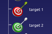
In the image below you can see two targets, the target 1 represented with a red color and the target 2 colored green.
The red color means the target is a cartesian target, and the green means it is a joint target.
Connect Through Firewall on windows
Note
This method was tested on Windows 10.
Check driver blockage
When connecting to a computer running Windows be aware that the firewall can prevent the connection to the robot. One option is to disable the firewall completely, but this is not recommended as it will leave your system vulnerable.
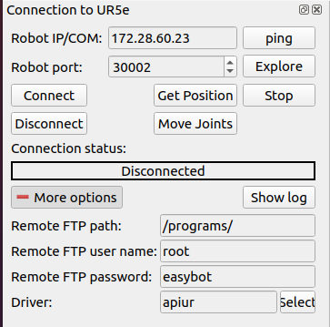
Instead, you can add a new rule to your windows firewall to allow communication only for the driver and IP address of the robot you use. To find these two attributes expand the connect to robot panel by choosing more options. In this case, the driver is apiur.
Go to the Windows Defender Firewall on your system and go into the Advanced settings. This will lead you to definitions of the firewall rules. Here the inbound rules can be changed to allow communications with the driver needed to control the robot.
Check in the inbound rules if the robot driver has a blocked sign. If the driver is blocked, disable this rule; otherwise, the firewall blocks communication.
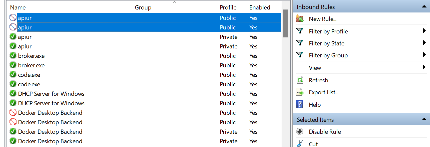
Once this rule is disabled, check if the RoboDK software can connect to the robot. If you can still not connect to the robot, you need to make a rule that specifically allows the driver to communicate with the robot.
Create a new inbound rule
By clicking New Rule… you create and define a rule that allows communication between your computer and the robot.

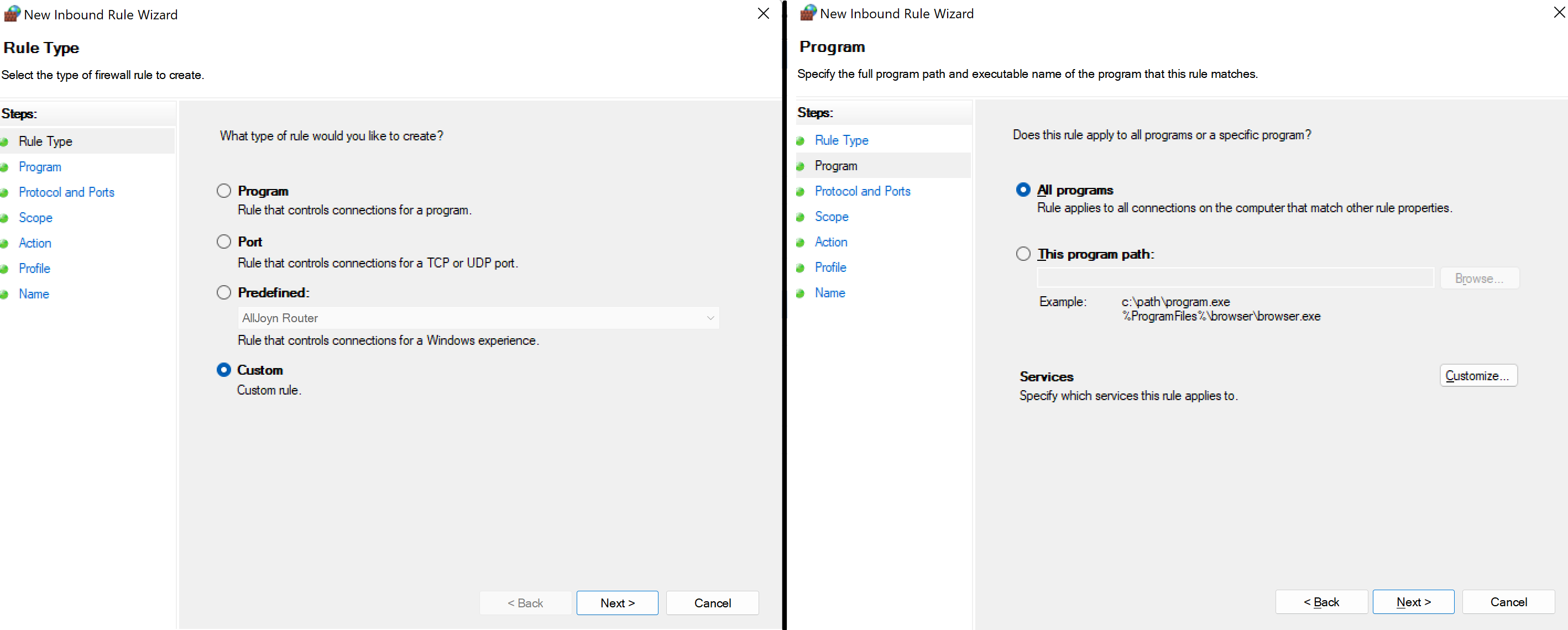
To begin with, you need to choose the option Custom on the first page and All programs on the second. you can find it illustrated below.
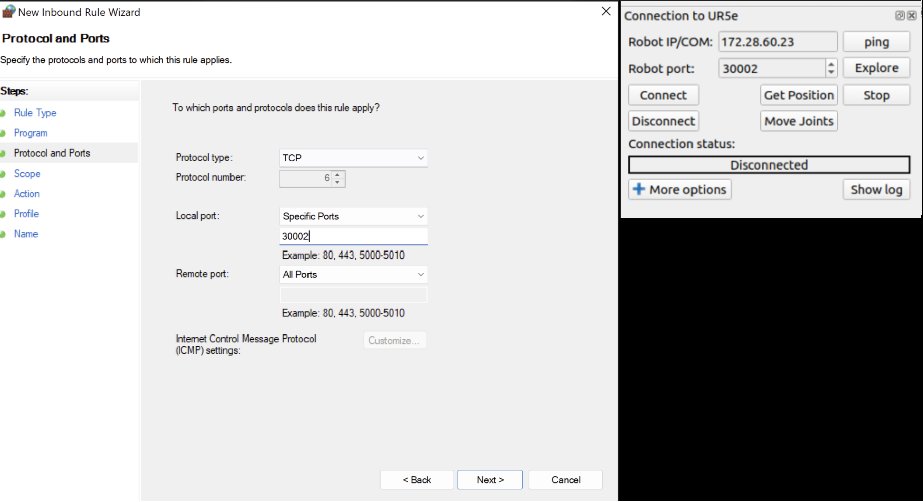
On the next page you need to choose the TCP as protocol, then choose a specific local port and insert the number of the port matching the one in RoboDK.
The next step is setting the IP address. Under Which remote IP address does this rule apply to?, choose These IP addresses. Then click on Add and set the IP that matches the one in RoboDK.
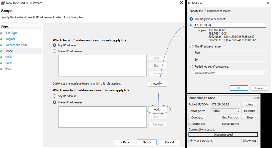
After hitting OK and Next, choose Allow all connections and on the next page, check all boxes.
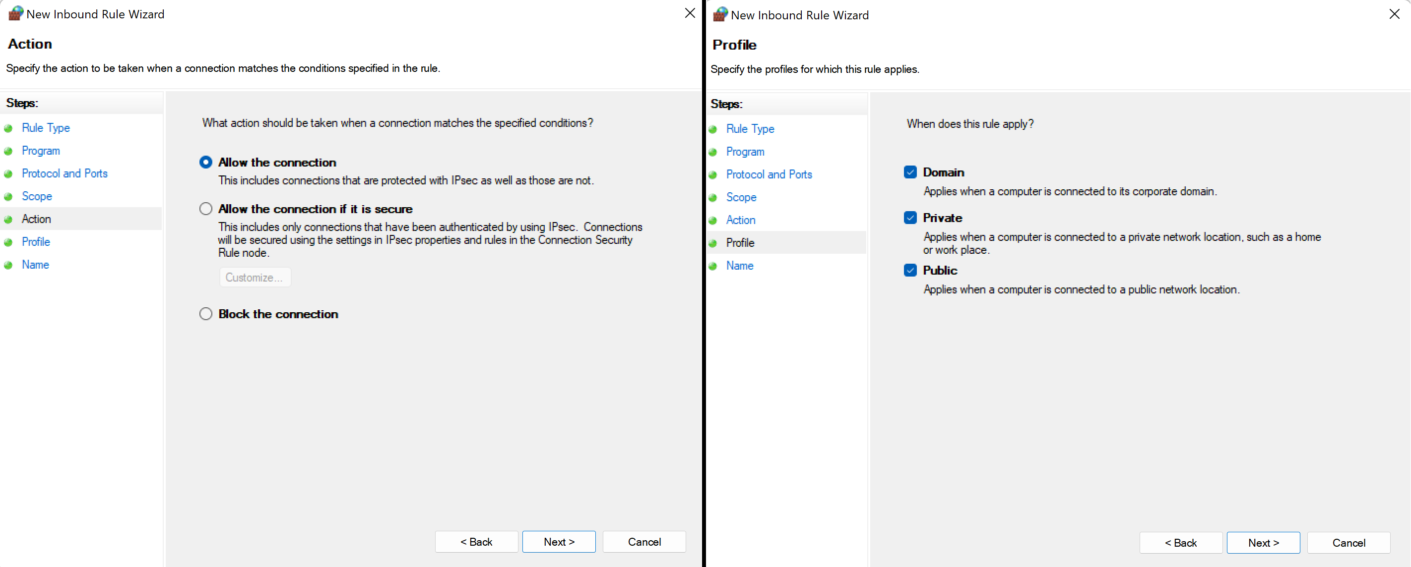
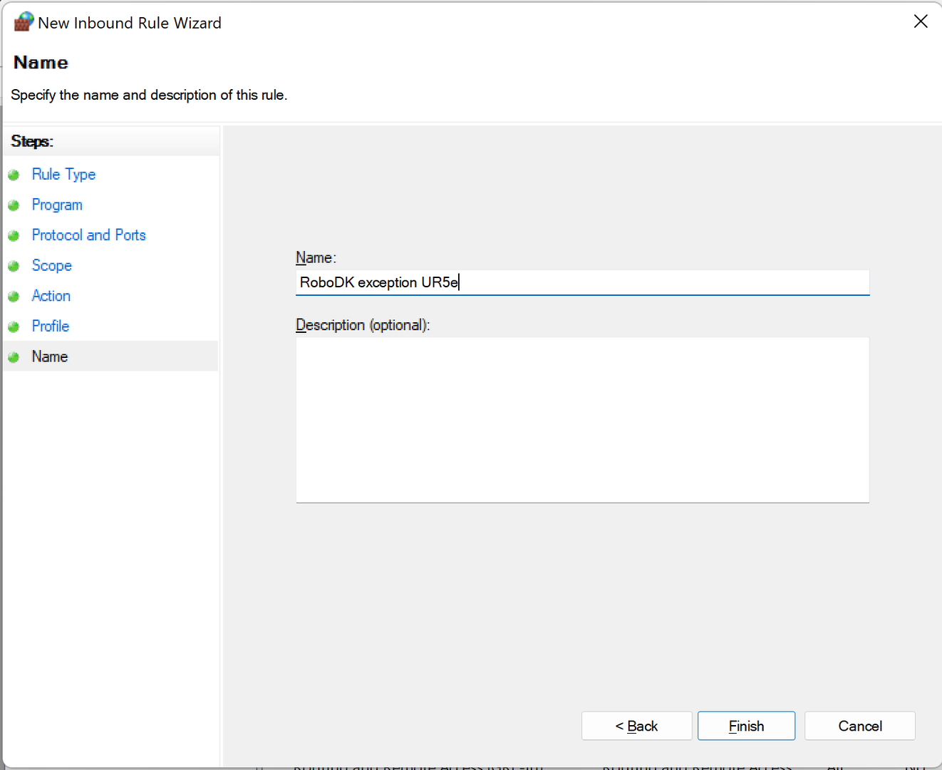
Finally, just choose a proper name for the rule, click Finish and you are good to go!
