基于ArUco标记的坐标转换
本教程展示了如何估计ArUco标记的位姿并使用4x4齐次变换矩阵将点云转换到ArUco标记坐标系。
小技巧
Zivid calibration board 包含了一个 ArUco 标记。
本教程使用了下图中显示的ArUco标记的点云。
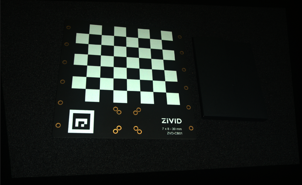
我们可以在Zivid Studio中打开 原始点云 并进行检查。
备注
原始点云在 Sample Data(示例数据) 中。
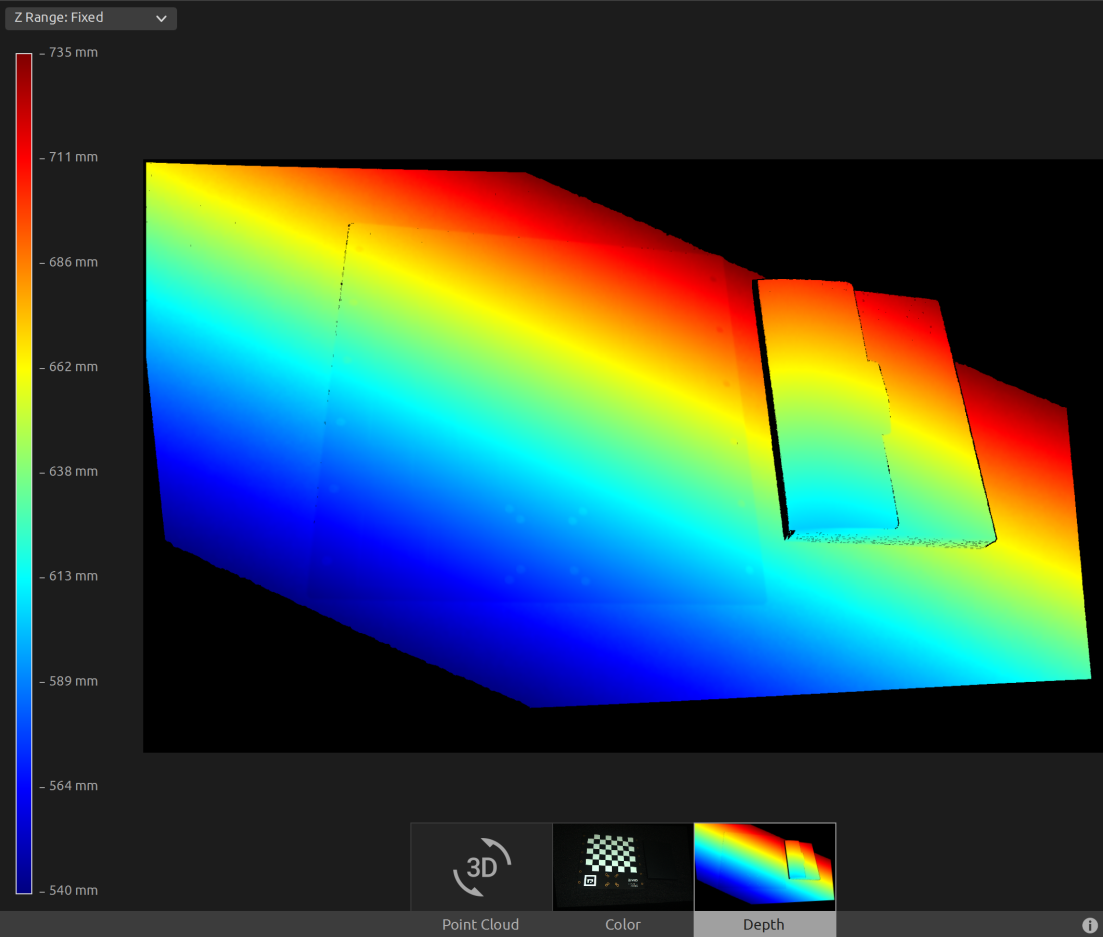
现在,我们可以将深度视图中的Z范围设置为540毫米至735毫米。我们可以看到标记在大约570毫米的距离处,并且相机和标记框之间存在一个角度。
首先,我们加载一个ArUco标记的点云。

const auto arucoMarkerFile = std::string(ZIVID_SAMPLE_DATA_DIR) + "/CalibrationBoardInCameraOrigin.zdf";
std::cout << "Reading ZDF frame from file: " << arucoMarkerFile << std::endl;
const auto frame = Zivid::Frame(arucoMarkerFile);
auto pointCloud = frame.pointCloud();
var calibrationBoardFile = Environment.GetFolderPath(Environment.SpecialFolder.CommonApplicationData)
               + "/Zivid/CalibrationBoardInCameraOrigin.zdf";
Console.WriteLine("Reading ZDF frame from file: " + calibrationBoardFile);

using (var frame = new Zivid.NET.Frame(calibrationBoardFile))
{
    var pointCloud = frame.PointCloud;
然后我们将配置ArUco标记。
std::cout << "Configuring ArUco marker" << std::endl;
const auto markerDictionary = Zivid::Calibration::MarkerDictionary::aruco4x4_50;
std::vector<int> markerId = { 1 };
Console.WriteLine("Configuring ArUco marker");
var markerDictionary = Zivid.NET.MarkerDictionary.Aruco4x4_50;
var markerId = new List<int> { 1 };
然后我们检测 ArUco 标记。
std::cout << "Detecting ArUco marker" << std::endl;
const auto detectionResult = Zivid::Calibration::detectMarkers(frame, markerId, markerDictionary);
Console.WriteLine("Detecting ArUco marker");
var detectionResult = Detector.DetectMarkers(frame, markerId, markerDictionary);
然后我们估计 ArUco 标记的位姿。
std::cout << "Estimating pose of detected ArUco marker" << std::endl;
const auto transformCameraToMarker = detectionResult.detectedMarkers()[0].pose().toMatrix();
Console.WriteLine("Estimating pose of detected ArUco marker");
var cameraToMarkerTransform = new Zivid.NET.Matrix4x4(detectionResult.DetectedMarkers()[0].Pose().ToMatrix());
在转换点云之前,我们先反转变换矩阵,以便得到相机在 ArUco 标记坐标系中的位姿。
std::cout << "Camera pose in ArUco marker frame:" << std::endl;
const auto markerToCameraTransform = transformCameraToMarker.inverse();
Console.WriteLine("Camera pose in ArUco marker frame:");
var markerToCameraTransform = cameraToMarkerTransform.Inverse();
转换后,我们将位姿保存到 YAML 文件中。
const auto transformFile = "ArUcoMarkerToCameraTransform.yaml";
std::cout << "Saving a YAML file with Inverted ArUco marker pose to file: " << transformFile << std::endl;
markerToCameraTransform.save(transformFile);
var transformFile = "ArUcoMarkerToCameraTransform.yaml";
Console.WriteLine("Saving a YAML file with Inverted ArUco marker pose to file: " + transformFile);
markerToCameraTransform.Save(transformFile);
这是 YAML 文件的内容:
__version__:
    serializer: 1
    data: 1
FloatMatrix:
    Data:
        [
            [0.978564, 0.0506282, 0.1996225, 21.54072],
            [-0.04527659, -0.892707, 0.4483572, -208.0268],
            [0.2009039, -0.4477845, -0.8712788, 547.6984],
之后,我们将点云转换到ArUco标记坐标系。
std::cout << "Transforming point cloud from camera frame to ArUco marker frame" << std::endl;
pointCloud.transform(markerToCameraTransform);
Console.WriteLine("Transforming point cloud from camera frame to ArUco marker frame");
pointCloud.Transform(markerToCameraTransform);
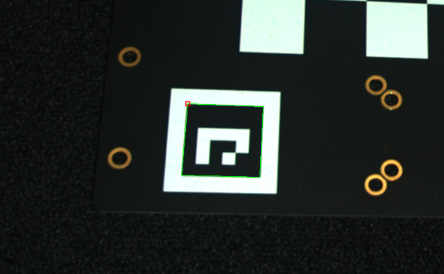
在保存转换后的点云之前,我们可以将其转换为OpenCV 2D图像格式并绘制检测到的ArUco标记。
std::cout << "Converting to OpenCV image format" << std::endl;
const auto bgraImage = pointCloudToColorBGRA_SRGB(pointCloud);
std::cout << "Displaying detected ArUco marker" << std::endl;
const auto bgr = drawDetectedMarker(bgraImage, detectionResult);
displayBGR(bgr, "ArucoMarkerDetected");
在这里我们可以看到将显示的图像,并且可以观察到棋盘格的坐标系在哪里。
最后我们将转换后的点云保存到磁盘。
const auto arucoMarkerTransformedFile = "CalibrationBoardInArucoMarkerOrigin.zdf";
std::cout << "Saving transformed point cloud to file: " << arucoMarkerTransformedFile << std::endl;
frame.save(arucoMarkerTransformedFile);
var arucoMarkerTransformedFile = "CalibrationBoardInArucoMarkerOrigin.zdf";
Console.WriteLine("Saving transformed point cloud to file: " + arucoMarkerTransformedFile);
frame.Save(arucoMarkerTransformedFile);
提示
了解更多关于 位置、方向和坐标变换。
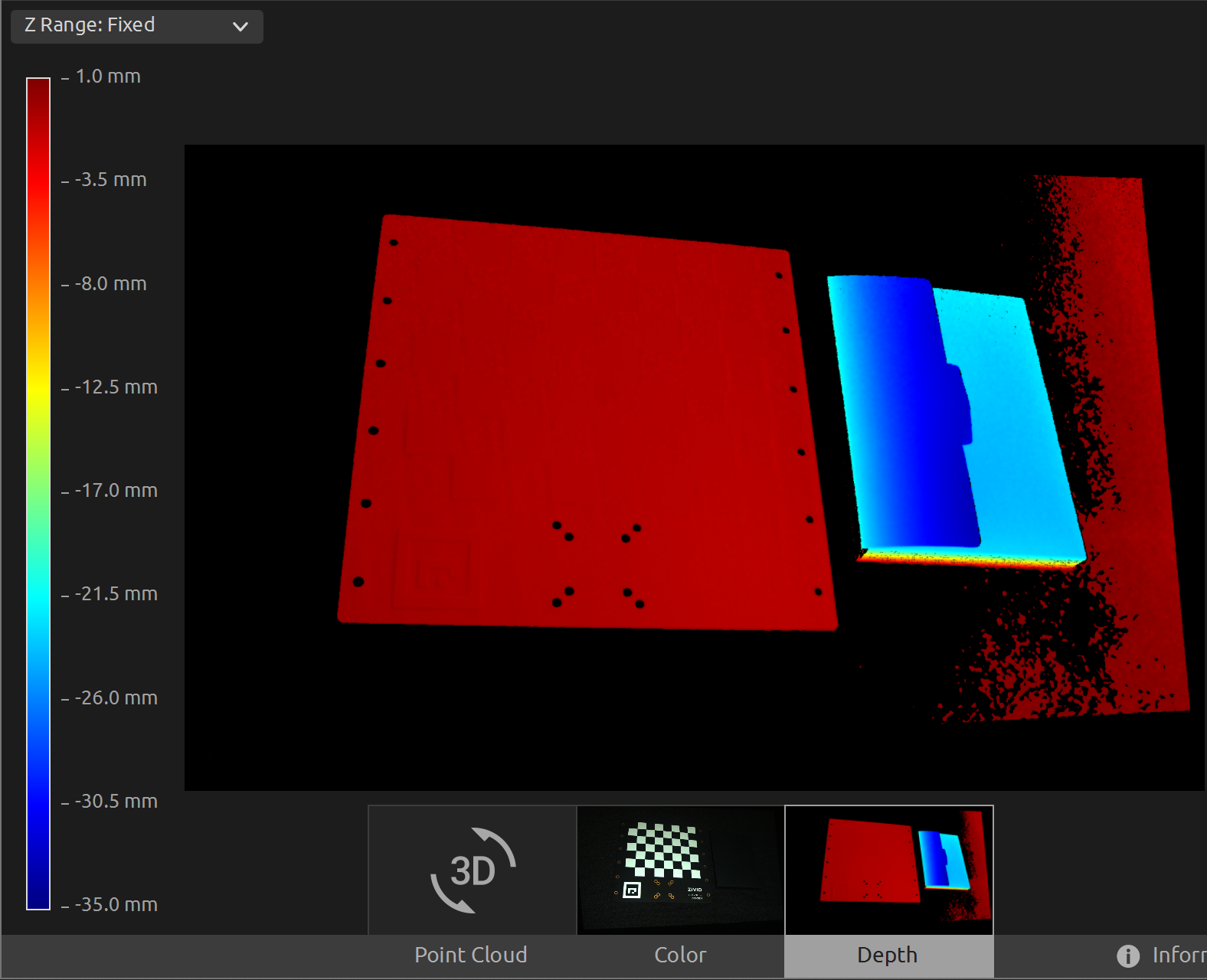
现在我们可以在Zivid Studio中打开 转换后的点云 进行检查。
备注
在Zivid Studio中缩小显示图像以查找数据,因为视点原点不适合观察转换后的点云。
我们现在可以在深度视图中手动将Z范围设置为-35mm至1mm,这样我们就可以过滤掉除了标定板和它旁边的物体之外的所有数据。这使我们可以看到我们在标定板上具有相同的Z值,并且从颜色渐变中我们可以检查该值是否为0。这意味着点云的原点位于ArUco标记上。
要将点云转换到 ArUco 标记坐标系,您可以运行我们的代码示例。
示例: TransformPointCloudViaArucoMarker.cpp
./TransformPointCloudViaArucoMarker
示例: TransformPointCloudViaArucoMarker.cs
./TransformPointCloudViaArucoMarker
示例: transform_point_cloud_via_aruco_marker.py
python transform_point_cloud_via_aruco_marker.py
小技巧
如果您希望在自己的设置中使用它,请修改代码示例:
用您的实际相机和设置替换 ZDF 文件。
将 ArUco 标记放置在场景中。
运行示例!