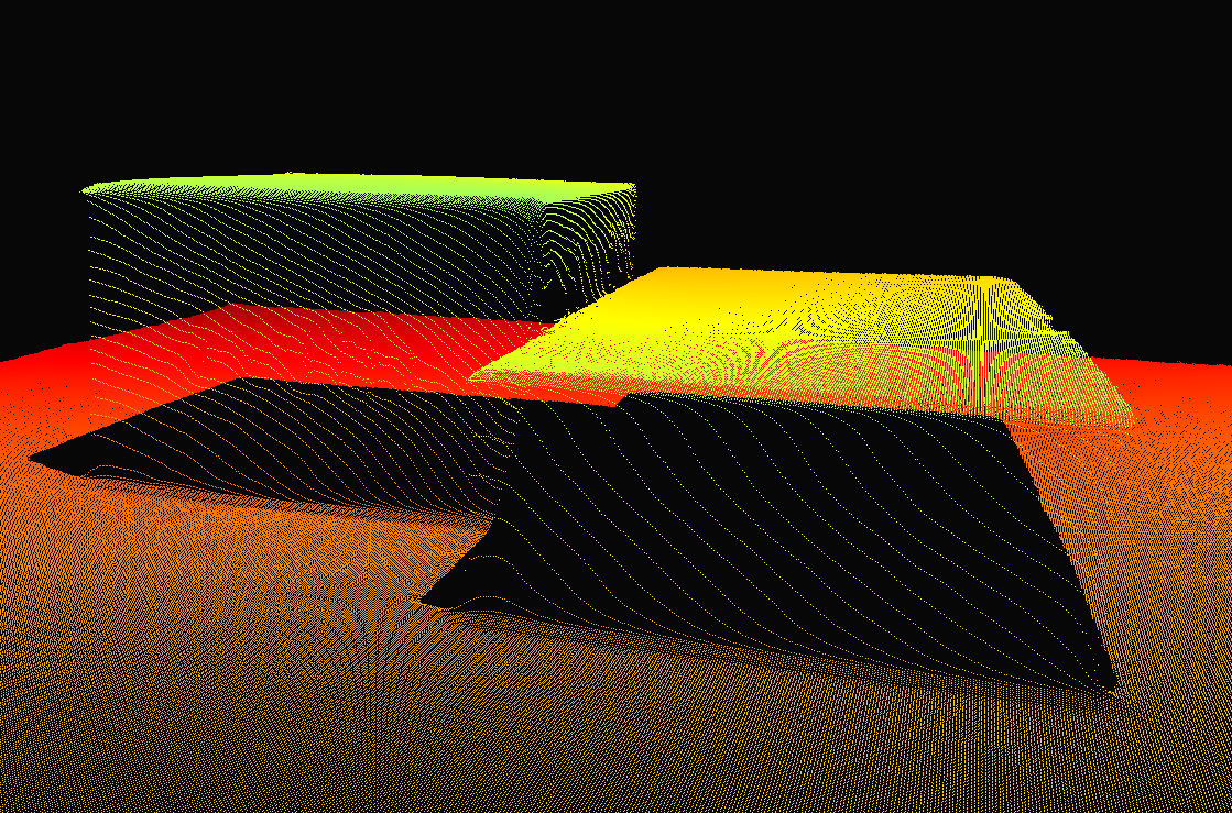
Adjusting Filters
Introduction
After exposure values and frames have been found as described in Getting the Right Exposure for Good Point Clouds, it is time to adjust filters. More information about the filters can be found here: Filters.
Cluster filter
The Cluster Filter removes floating points and isolated clusters from the point cloud.
Tip
This filter is especially useful if you use collision avoidance while picking objects. Let’s say there is a cluster of points above an object, but that cluster doesn’t exist in the reality. The robot can interpret such floating clusters as real obstacles instead of something it can physically collide with. That can lead to undesirable picking poses of the object or even the inability to pick it.
How to control the Cluster Filter
EnabledTurn the filter On/Off
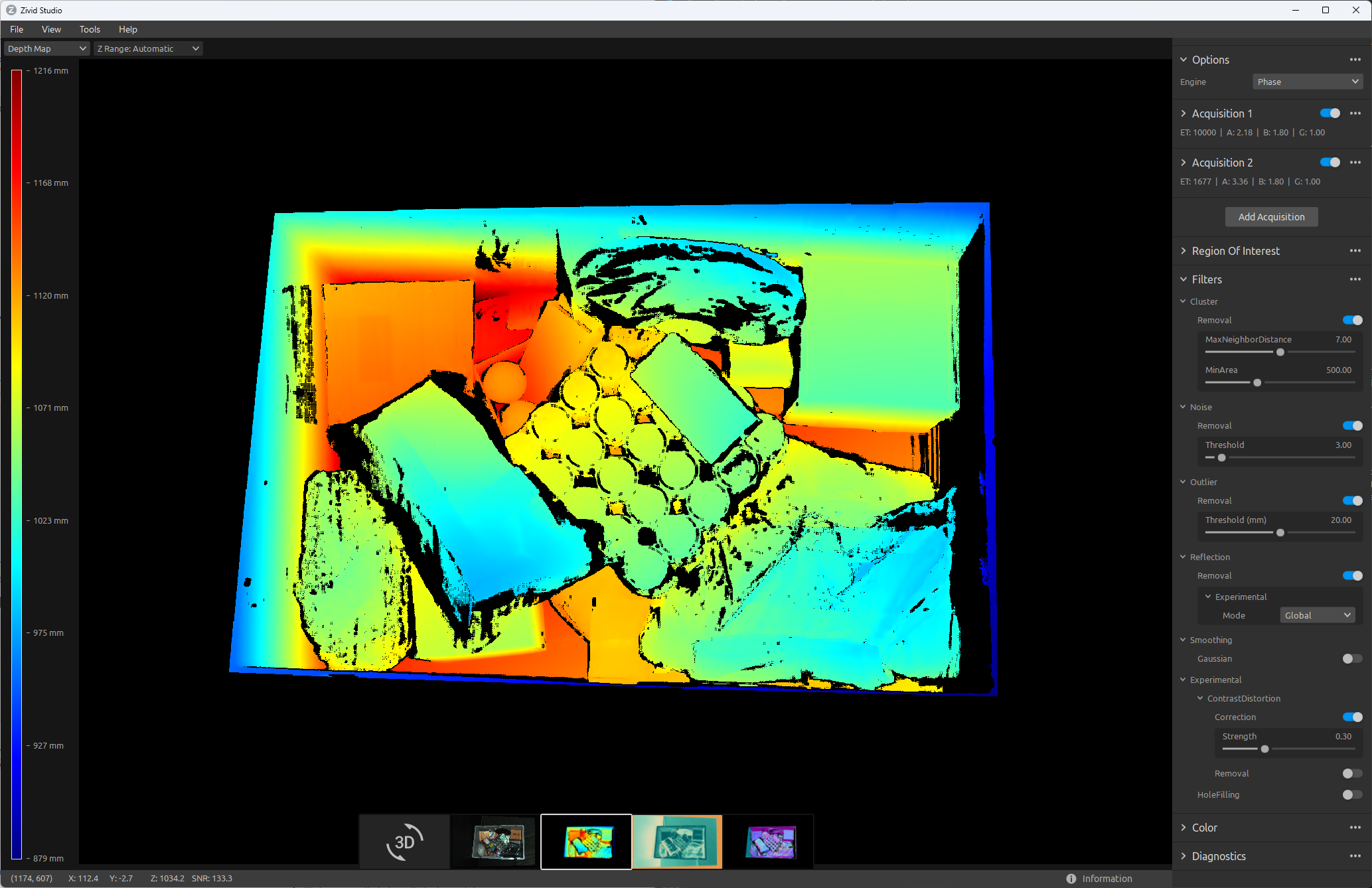
MaxNeighborDistanceMaximum normalized distance between neighboring points that are still classified as belonging to the same cluster. The filter removes clusters whose neighboring points are further away than the MaxNeighborDistance (clusters less dense than this threshold). The lower the value, the more aggressive the filtering.
MinAreaArea of the cluster, in square millimeters. The filter removes clusters with an area below this threshold. Increasing this parameter results in removing larger clusters.
For a point to be removed, it must belong to a cluster that meets the MaxNeighborDistance and the MinArea requirements.
Parameter |
Value |
Condition |
|---|---|---|
|
|
If you do not have floating points, isolated clusters, or if you cannot afford the added processing time |
|
If you want to remove floating points or isolated clusters |
|
|
|
Sparse clusters, works for most scenes |
|
Dense clusters |
|
|
Very dense clusters, normally originated by reflections |
|
|
|
For clusters that the Outlier Filter failed to remove |
|
For clusters of typical size |
|
|
For removing ghost planes, typically caused by reflections |
Removing floating clusters
The Noise Filter and the Outlier Filter are basic removal filters that are almost always used. These filters together with the Reflection Filter (especially the local mode) may not be able to remove all the floating points and clusters without removing too many good points. This is typically the case for challenging scenes. The Cluster filter can remove the remaining erroneous points without removing good data from the rest of the scene.
Complementing the Outlier Filter
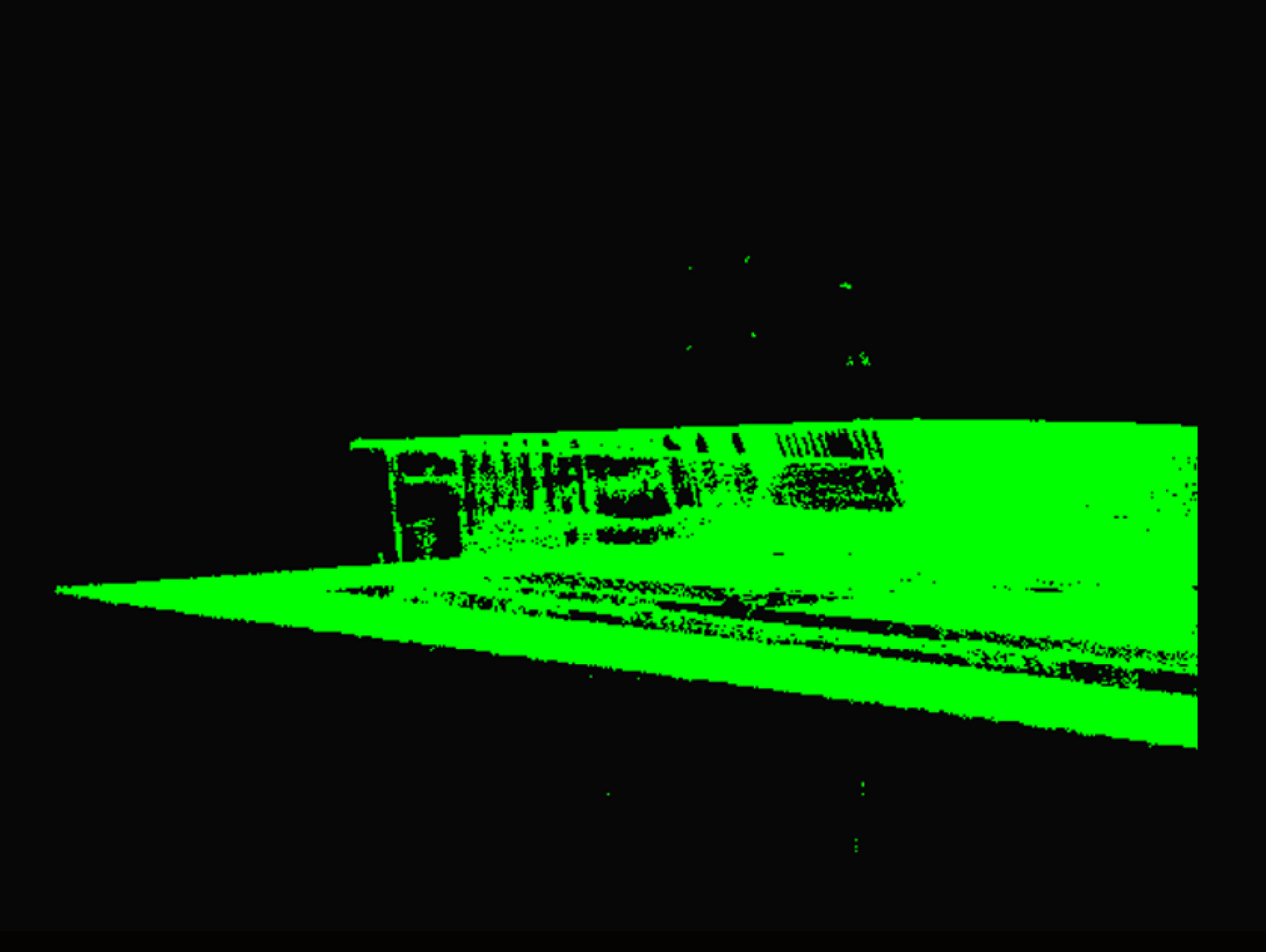
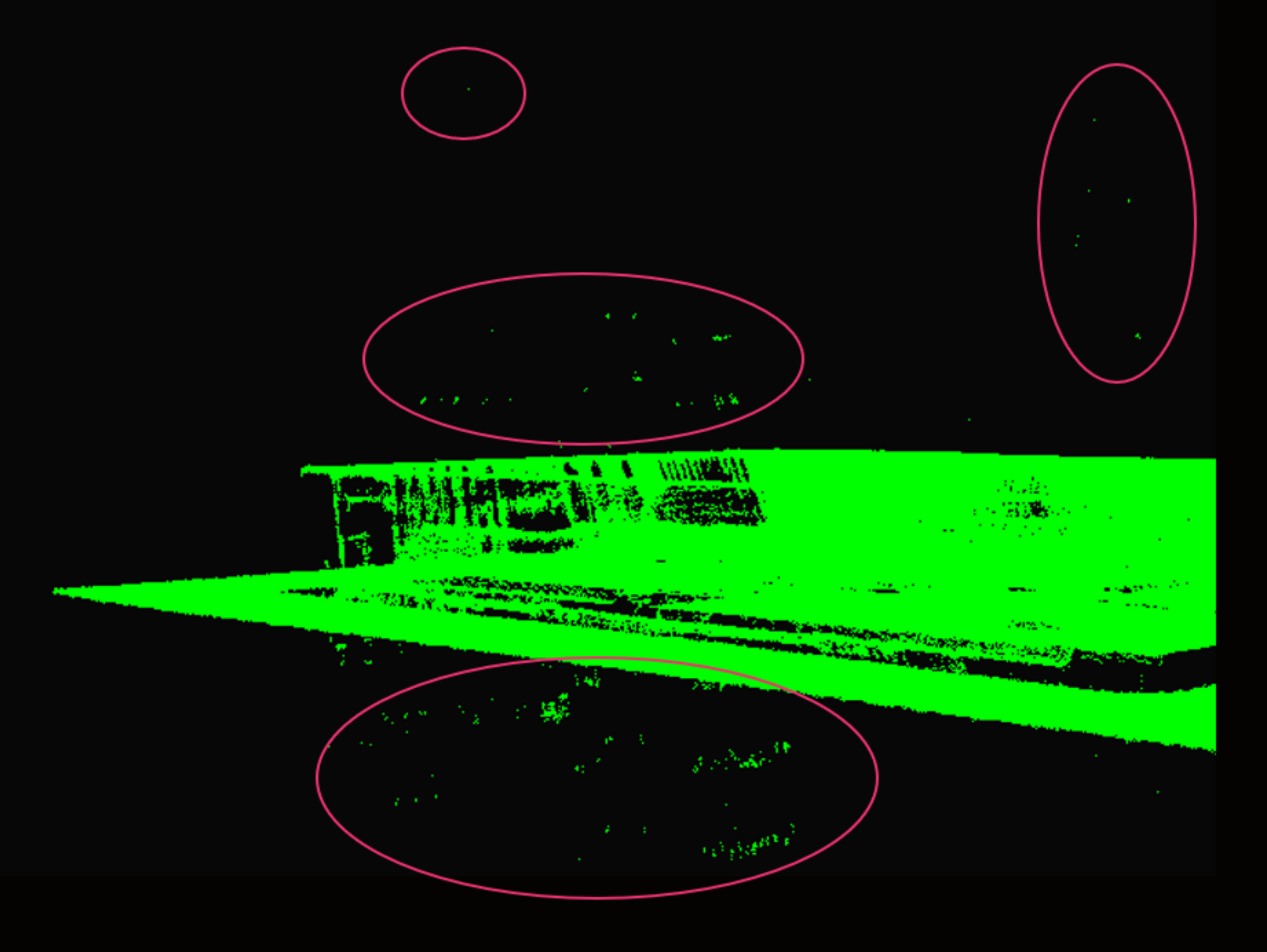
In the following image, the Cluster Filter is turned off and we can see collections of floating points in different sizes and densities.
In the bottom left image, we see how the Outlier filter behaves when it’s the most strict possible, keeping some floating points while removing good points. In the bottom right image, we see how the Cluster filter (with default values in this case) removes these floating points while keeping the good points intact.
Complementing the Reflection Filter - Local mode
The Reflection Filter, especially with the Local mode, can leave more groups of points floating; take a look at the bottom left image. In the bottom right image, we can see that these floating points are removed using the Cluster Filter (with default values in this case).
Removing ghost planes
Ghost planes are false point cloud data that do not exist in reality and usually result from interreflections between the objects or interreflections with the bin wall. One end of these clusters of floating points is typically connected with a point cloud surface comprised of good data. Removing ghost planes is sometimes possible by fine-tuning the Cluster Filter. These artifacts are usually dense and have a large area. Therefore, the filter must be tuned aggressively, which can result in removing some good data, including parts of objects or whole objects.
Warning
When using the cluster filter to remove ghost planes, carefully observe whether any critical data is removed.
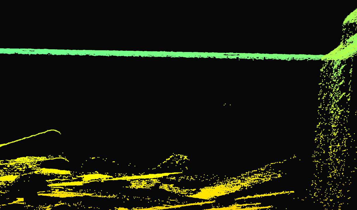
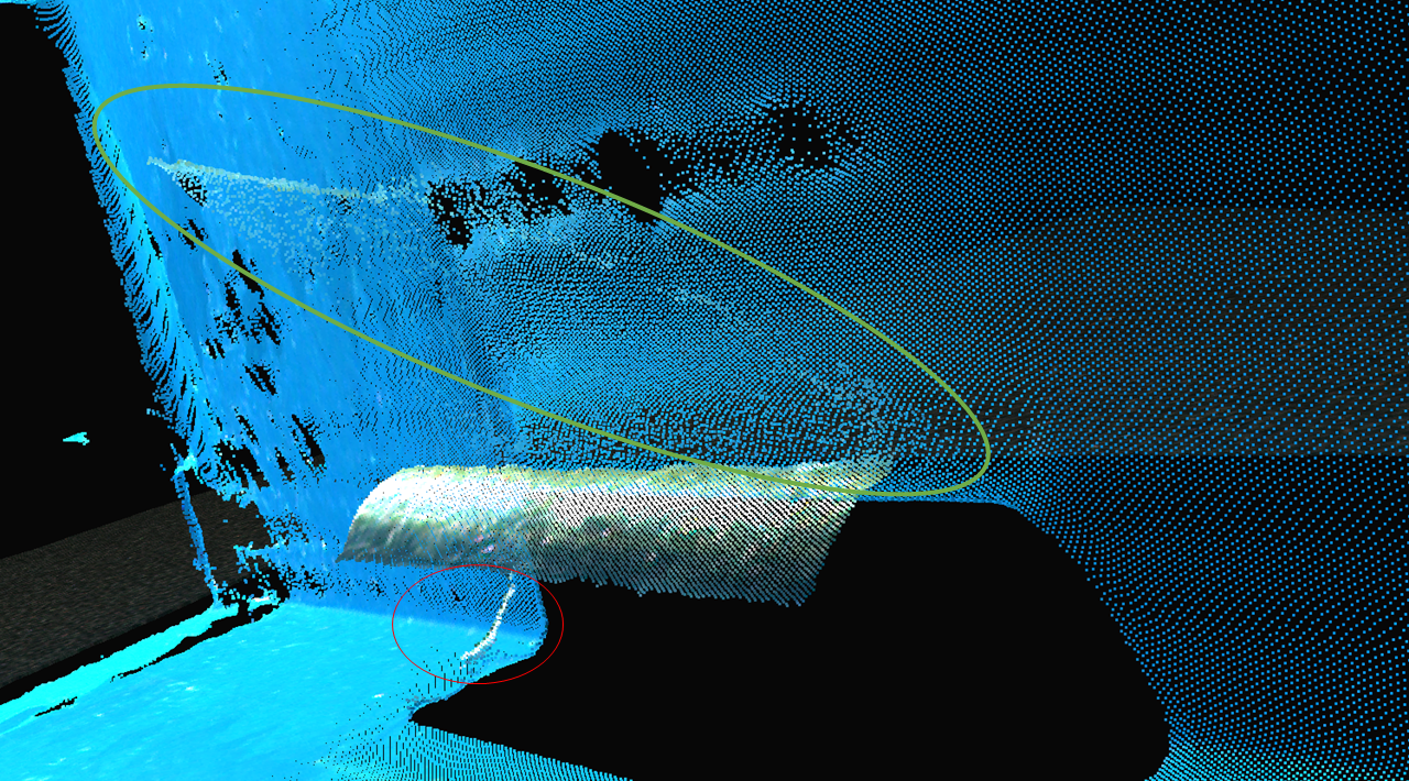
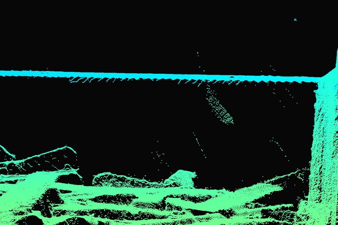
In the following example scene, a ghost plane above the cylinder appears due to the reflection between the top of the cylinder and the bin wall. Notice that in the color image, we can see the reflection of the cylinder on the top bin wall.
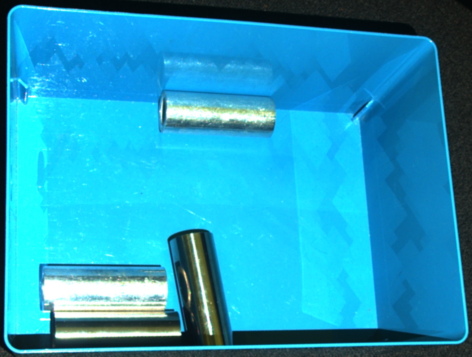
This ghost plane (bottom left image) may be interpreted as an obstacle for the robot to pick the object.
Such obstacles can result in getting an undesirable picking pose or even no picking pose at all.
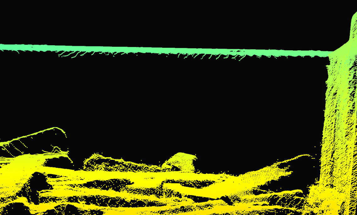
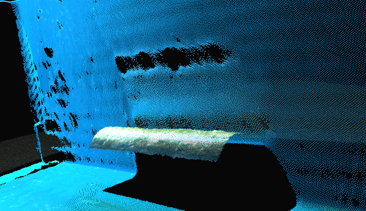
In the bottom right image, we can see that the ghost plane is removed by tuning the Cluster Filter aggressively.
In this example, the MaxNeighborDistance is set to 5.00 and the MinArea to 1400.00.
As a trade-off, the bottom part of the cylinder is removed as well.
Tuning the cluster filter to remove ghost planes is easier if the bin contains a single type of object.
This is because it is possible to determine the area of the smallest object feature in the point cloud that needs to be kept.
Then, the MinArea can be set accordingly.
Warning
When using Intel GPU, the Cluster Filter can significantly increase the processing time.
Hole Repair
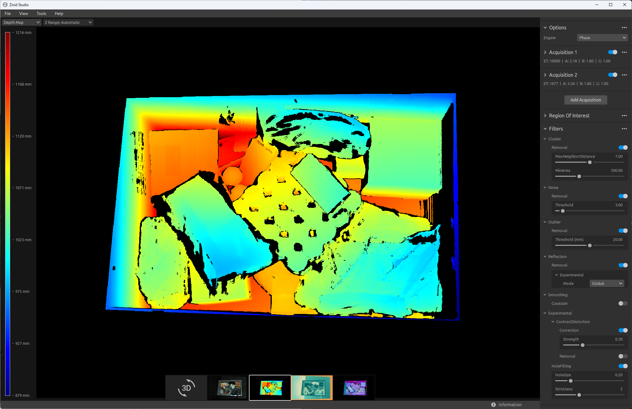
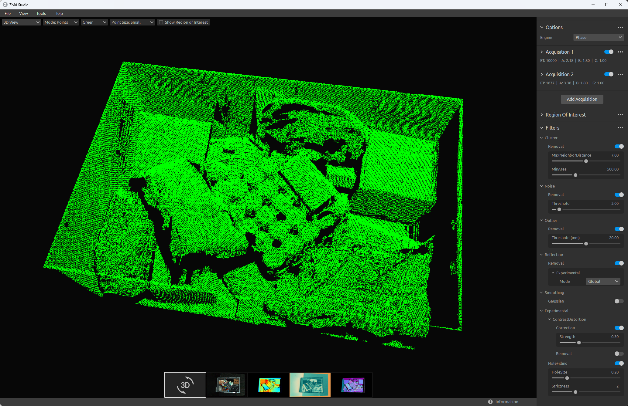
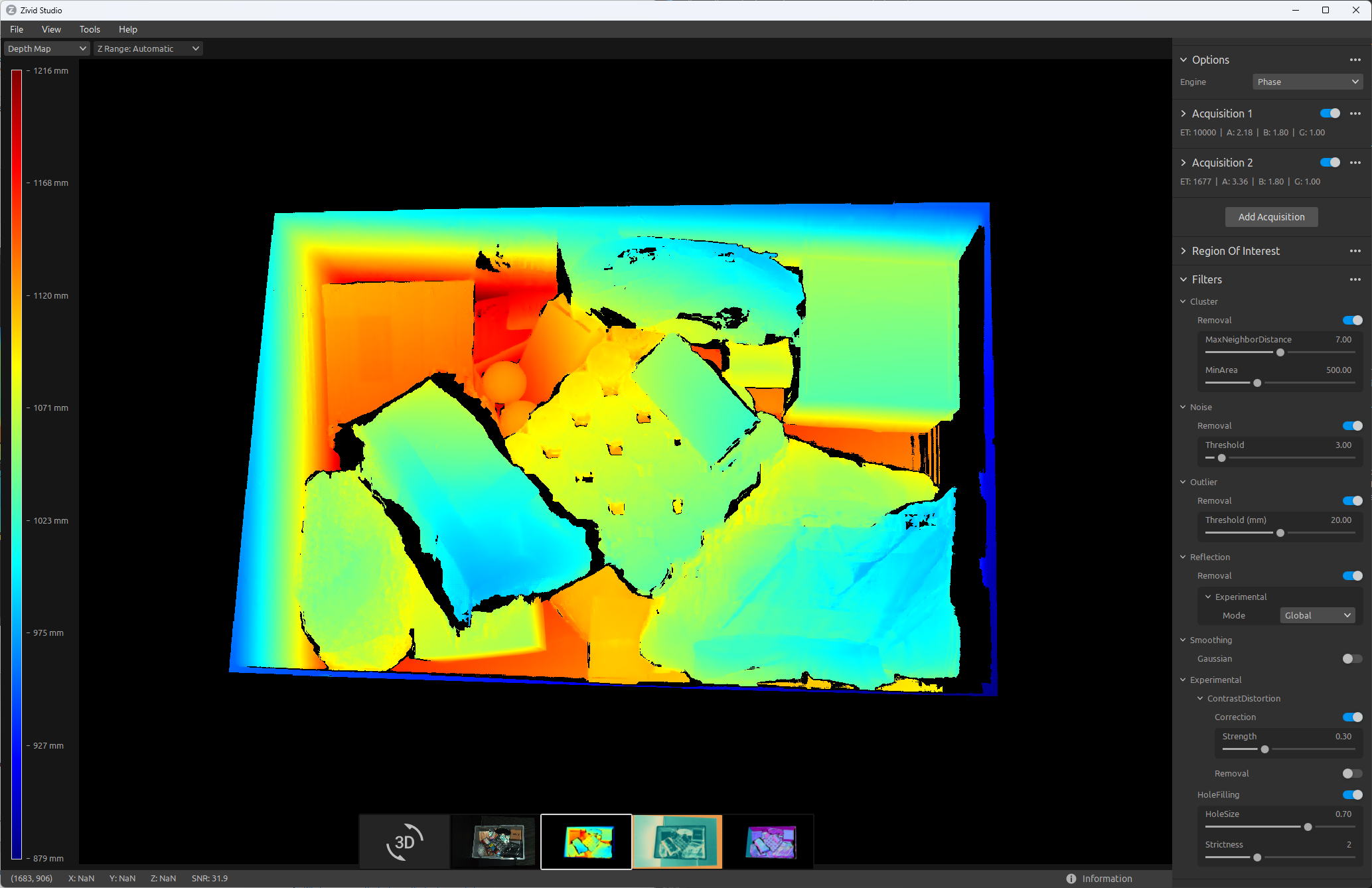
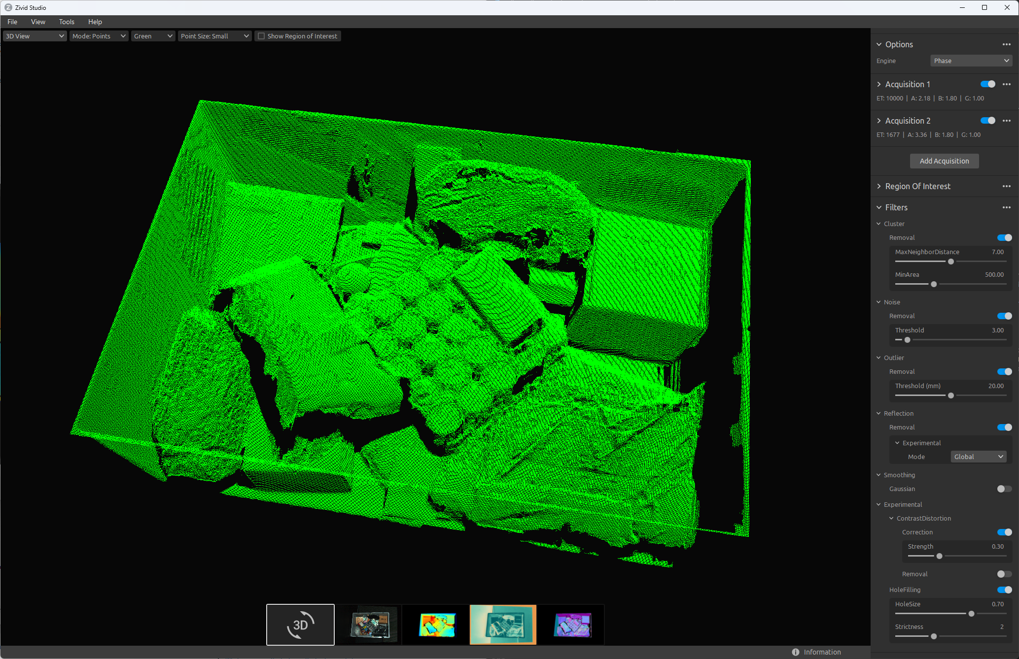
The Hole Repair filter fills missing points in the point cloud. It interpolates remaining points in a circular neighborhood around the missing points in the point cloud. The missing points may have been removed by other filters, or not reconstructed in the first place.
Note
It is recommended to apply Removal Filters before adding Hole Repair filter. This prevents interpolation of noisy points.
EnabledTurn the filter On/Off
HoleSizeRelative diameter of holes to fill. Increasing this will fill more points, but require more computation time. The maximum allowed hole size scales with distance, so that we allow filling larger holes at greater distances, measured in mm.
StrictnessLevel of strictness when considering if a point should be filled. A higher level of strictness requires a missing point to be surrounded by valid points on more sides in order to be filled. Increasing this will fill fewer points, but it will be less likely to fill gaps that are not circular, for example between two edges.
The following values should be used:
Parameter |
Value |
Condition |
|---|---|---|
|
|
If you do not accept inferred data, or if you cannot afford the added processing time. |
|
If your algorithm requires higher point cloud density, and you currently have an issue with sparse point clouds. |
|
|
|
Only fill the very smallest holes (fast) |
|
(Default) Fill holes with an approximate diameter of ~8 mm at 1000 mm distance [1] |
|
|
Fill large holes with an approximate diameter of ~25 mm at 1000 mm distance [1] (slow) |
|
|
|
Fill holes even when there are few valid points in the circular neighborhood |
|
Only fill holes that are surrounded by valid points in the circular neighborhood |
Consider the following scene with a bin filled with consumer goods:
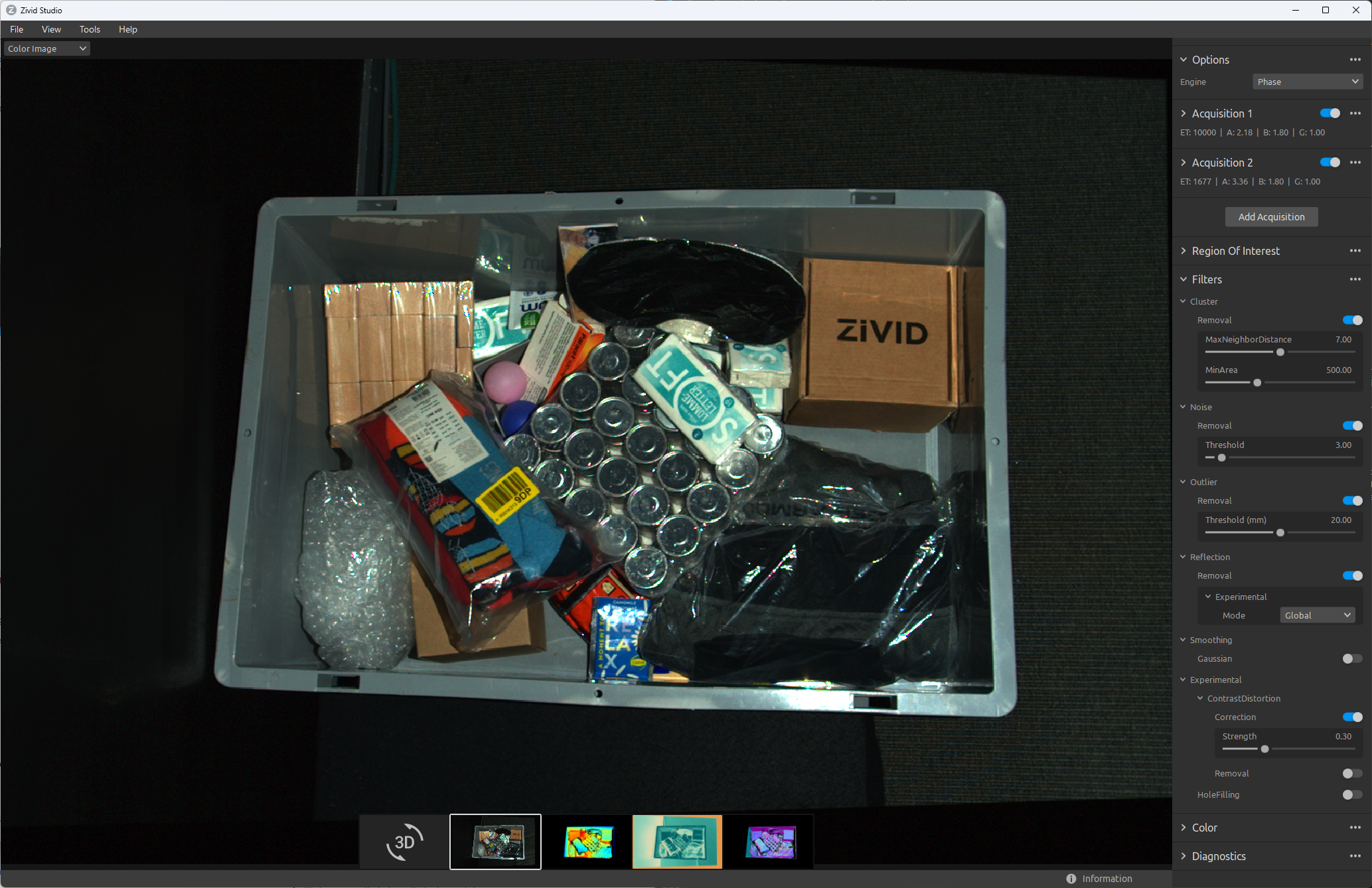
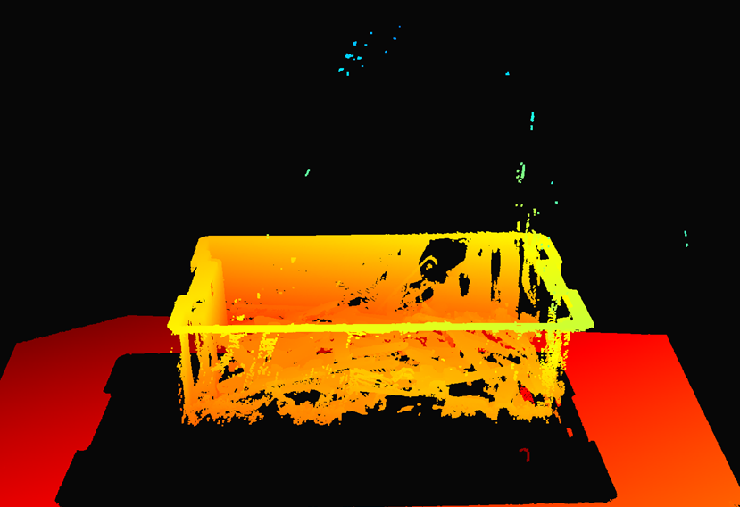
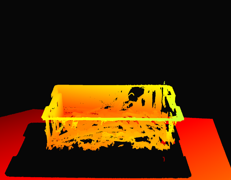
With the fast preset for Consumer Goods you get the result on the left below. Now, compare that with default and strong Hole Repair. This may be what makes it possible to calculate a good grasp pose on all items.
Hole Repair filter disabled
Hole Repair filter 0.2 (default)
Hole Repair filter 0.27 (strong)
Hole Repair filter adds the following processing time per 3D capture:
Noise filter
The purpose of Noise Filter is to clean up a noisy point cloud.
Removal
The Signal-to-Noise-Ratio (SNR) filter removes points where the SNR of the projected pattern signal is below the specified limit (see Detectable Light Intensity in a Camera Capture). Points with low SNR values will be noisier (e.g. due to ambient light), and the SNR filter can, therefore, be used to preserve only the points that are deemed acceptable.
In some inspection cases, it may be desired to only preserve points with high confidence. In bin-picking scenarios, however, noisier points are typically regarded as better than no points at all. This is because, ultimately, the matching algorithm will decide whether or not the match it found is satisfactory or not.
Parameter |
Value |
Condition |
|---|---|---|
|
|
If you want to keep all points regardless of their SNR values (rarely) |
|
If you want to control the quality of the point cloud by filtering out the points with low SNR values (usually) |
|
|
|
If you want to maximize the surface coverage but still filter out some points with low confidence, e.g., for Parcel Picking |
|
If you want to keep only decent quality points, for most applications, e.g., Manufacturing (Bin Picking) and E-commerce (Piece Picking).
Use lower threshold values ( |
|
|
If you want to keep only points with high confidence, e.g., Quality Inspection |
Hint
SNR threshold value of 3 yields a good tradeoff between discarded points and noise.
Note
Noise Removal (SNR) filter adds close to no additional processing time.
For more information about the SNR value see SNR Value.
Repair
This filter repairs the regions of missing data due to noisy points.
Value |
Condition |
|
If you require all points in your point cloud to be of high confidence. |
|
If you want to maximize the surface coverage. |
Note
Noise Repair adds additional processing time. Enabling Noise Repair and Noise Suppression adds the same processing time as enabling only one of them.
Suppression
This filter reduces noise and outliers in the point cloud.
Value |
Condition |
|
If you need to distinguish very fine details and thus need to avoid any smoothing effects. |
|
If you want to reduce noise and outliers in the point cloud or reduce ripple effects caused by interreflections. |
Note
Noise Suppression adds additional processing time. Enabling Noise Suppression and Noise Repair adds the same processing time as enabling only one of them.
Outlier filter
The Outlier filter removes pixels that it deems as outliers within a small local region of neighboring pixels. The outliers are measured by how far away they are from their closest neighbors. If the distance exceeds the threshold of the Outlier filter, the pixel is identified as an outlier and thus removed from the final point cloud. The unit of the Outlier filter threshold is in millimeters, and the smaller the threshold, the more pixels are removed. It is recommended to start with a relaxed Outlier filter and then tighten the threshold until you are satisfied with the density/noise level.
Value(mm) |
Considerations |
5-20 |
Typical (lower values for short distances, higher values for long distances). |
50-100 |
Can be considered if using the camera in one of the following conditions:
|
OFF |
If you have extreme noise and need to keep as many points as possible, you can turn the filter off. This is useful in extremely dark scenes, at the edge or outside of the camera’s range, or outdoors. |
Note
The unit for the Outlier filter is in millimeters
Note
The outlier filter adds close to no additional processing time.
Reflection filter
The Reflection filter removes points that Zivid deem as impacted by reflection and thus erroneous. These are typically seen in the point cloud as “ghost planes” - small regions of points floating mid-air that shouldn’t be there.
The following values should be used:
Value |
Condition |
|
If you know that your scene is not reflective, and you want to optimize acquisition time. |
|
Turn on if you have issues detecting parts that are reflective or are inside a reflective bin. |
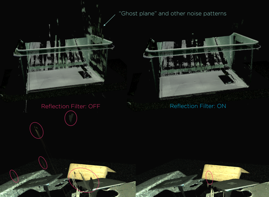
The Reflection filter has two modes: Global (default) and Local. These modes have different benefits and downsides, depending on the used Vision engine.
Mode |
Pros |
|
|
|
|
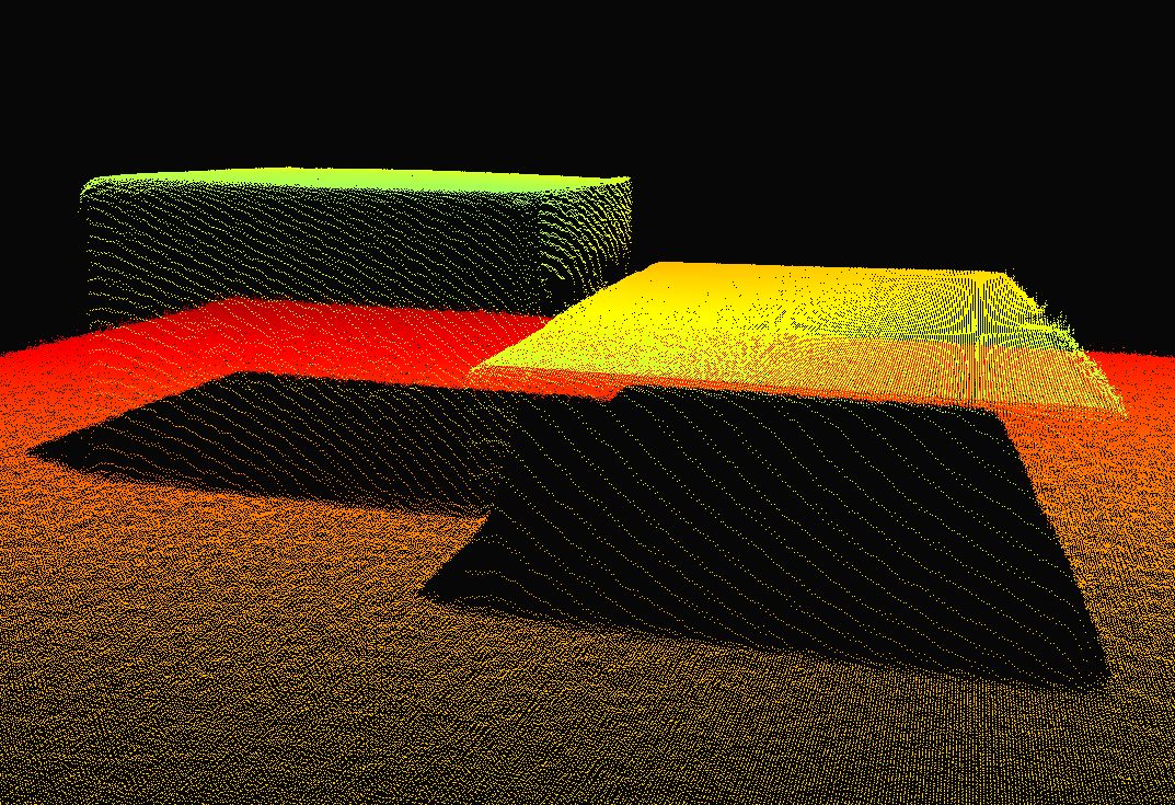
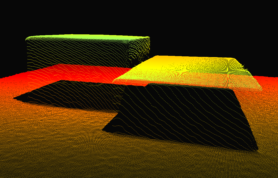
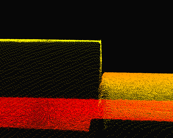
The images below highlight the main advantage of Global mode, its higher dynamic range, as can be seen on the coverage on shiny black objects in this scene.
Although Local mode has a reduced dynamic range, this can be compensated for by increasing the exposure time, as demonstrated in the comparison images.
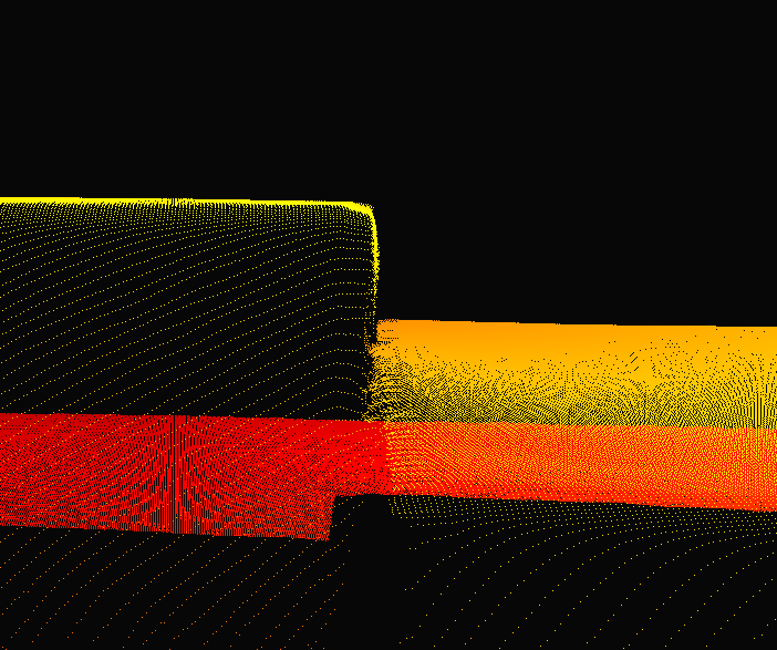
The images below illustrate the benefits of Local mode.
Mode |
Pros |
|
|
|
|
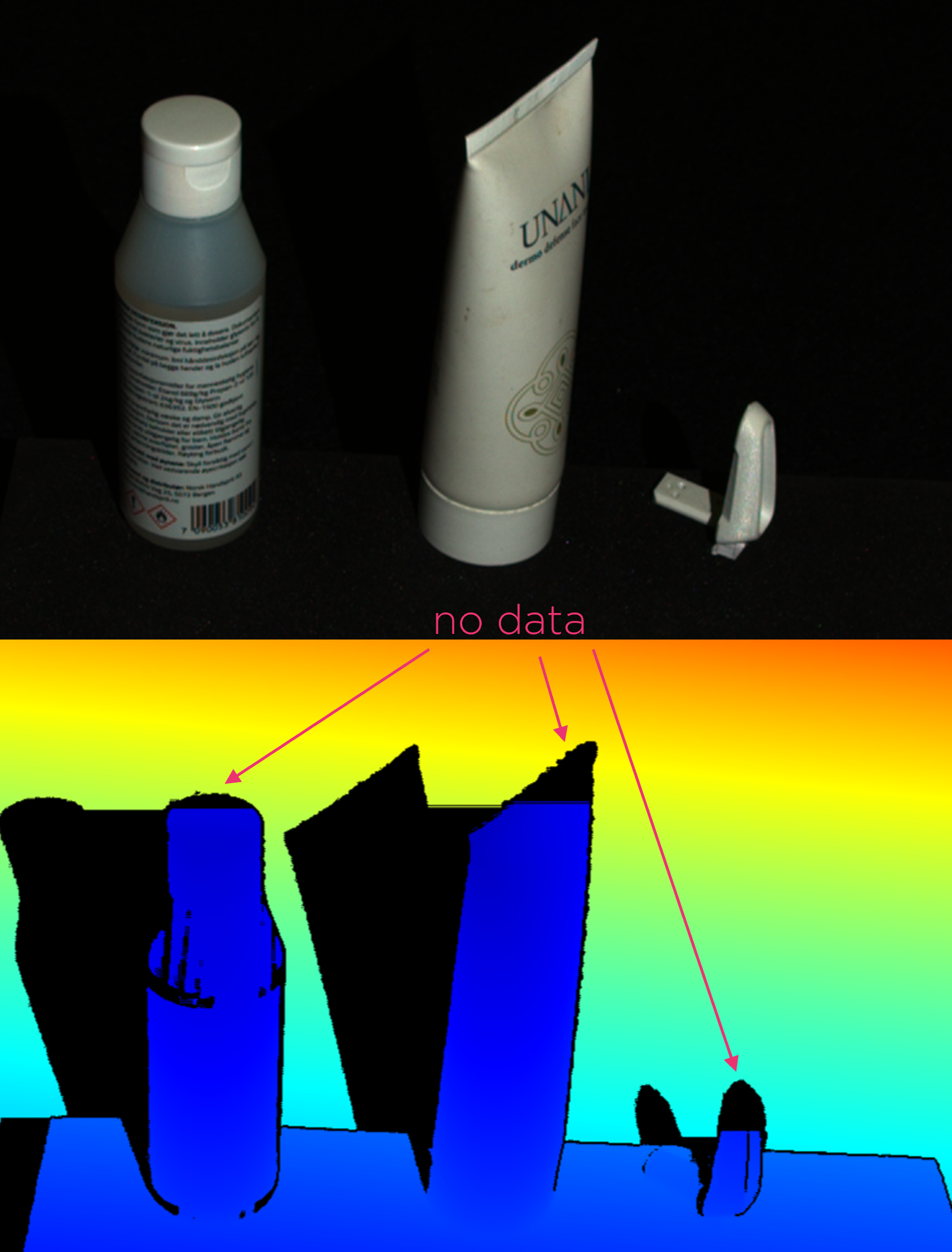
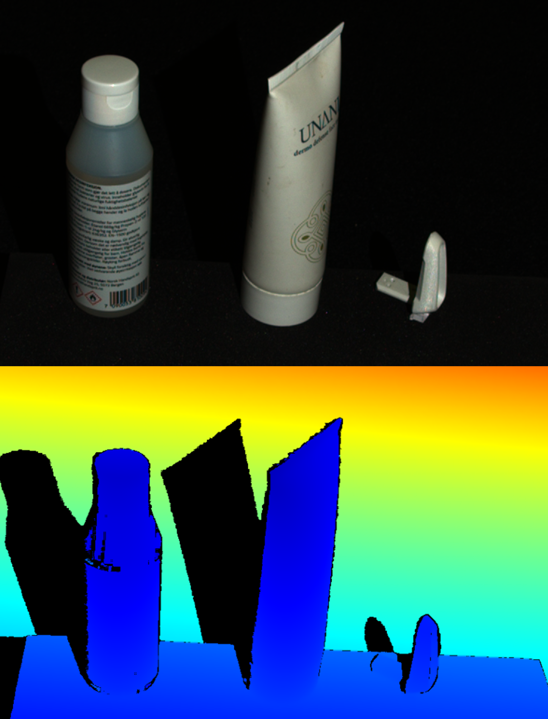
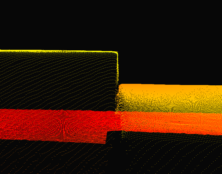
The images below highlight the main advantages of Global mode: better data on object sides and edges, and fewer outliers.
The floating points (outliers) that Local mode cannot remove are typically removed by the Cluster Filter.
The images below illustrate the benefits of Local mode: preserving data on thin and pointy objects.
Reflection filter (Global mode) adds the following processing time per 3D capture:
No additional processing time is added when using the Omni engine.
Gaussian smoothing
The Gaussian filter performs smoothing of points within a small local region based on 3D distances.
This can be used to suppress sparse noise, correct outliers, and align points to a grid.
Sigma parameter defines the aggressiveness of the filter.
The higher the sigma, the more aggressive smoothing.
Note that the Gaussian filter can, in many cases, correct outliers, but high sigma will also smooth out edges.
Value |
Condition |
<1.0 |
If you want to preserve as many details and features as possible. Preferred with small objects (sub-cm features). |
1.5 |
For most conditions and medium sized objects. |
2.5-5 |
If you care about smoother and larger surfaces such as flatness of a plane. |
Gaussian filter adds the following processing time per 3D capture:
Contrast Distortion filter
The Contrast Distortion filter corrects and/or removes points that are affected by blurring in the camera lens. In the point cloud, this typically occurs in regions with high contrast (strong specular reflection), and in regions with large texture gradients. The artifact is explained in detail in Contrast Distortion Artifact.
The filter parameter strength states how much a point is corrected in 3D space, and threshold indicates the maximum distance before a point is removed (if removal mode is on). As strength and removal depend on camera focus and orientation (to camera baseline) of the object, its recommended to first tune exposure settings before tuning Contrast Distortion Filter parameters.
Warning
If the strength value is very high, it may overcompensate correction.
Tip
Turning off Contrast Distortion helps to preserve the sharpness of 3D edges.
Value |
Condition |
0.1 - 0.2 |
If you have small contrast distortion effects and no-to-little correction is needed. |
0.3 - 0.5 |
“Almost always”, if your camera has good focus, but contrast distortion is present. Some correction is needed. |
0.6 - 0.7 |
“Common”, if your point cloud is affected by a large contrast distortion. Your camera may be a bit out of focus. |
0.8 - 1.0 |
“Uncommon”, if you have a very high effect of contrast distortion. This often indicates that the camera is out of focus! |
Contrast Distortion filter adds the following processing time per 3D capture:
Tip
If Contrast Distortion Correction filter is already enabled, then Contrast Distortion Removal adds negligible processing time.
Tuning Aperture before Contrast Distortion filter
Note
Zivid 3 does not have an adjustable aperture. The following information about aperture tuning applies only to Zivid 2 and Zivid 2+ cameras.
Tuning the Contrast Distortion filter is sometimes not sufficient to remove contrast distortion artifacts. The artifacts get worse with blurry color images. Therefore, it is important to ensure the color image is in focus by tuning the Aperture before tuning the filter.
We will demonstrate the process of removing contrast distortion artifacts by tuning the Aperture with an example.
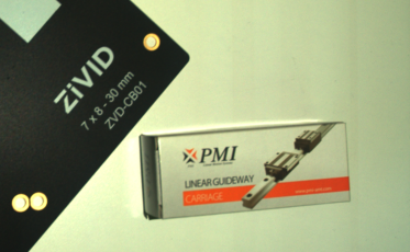
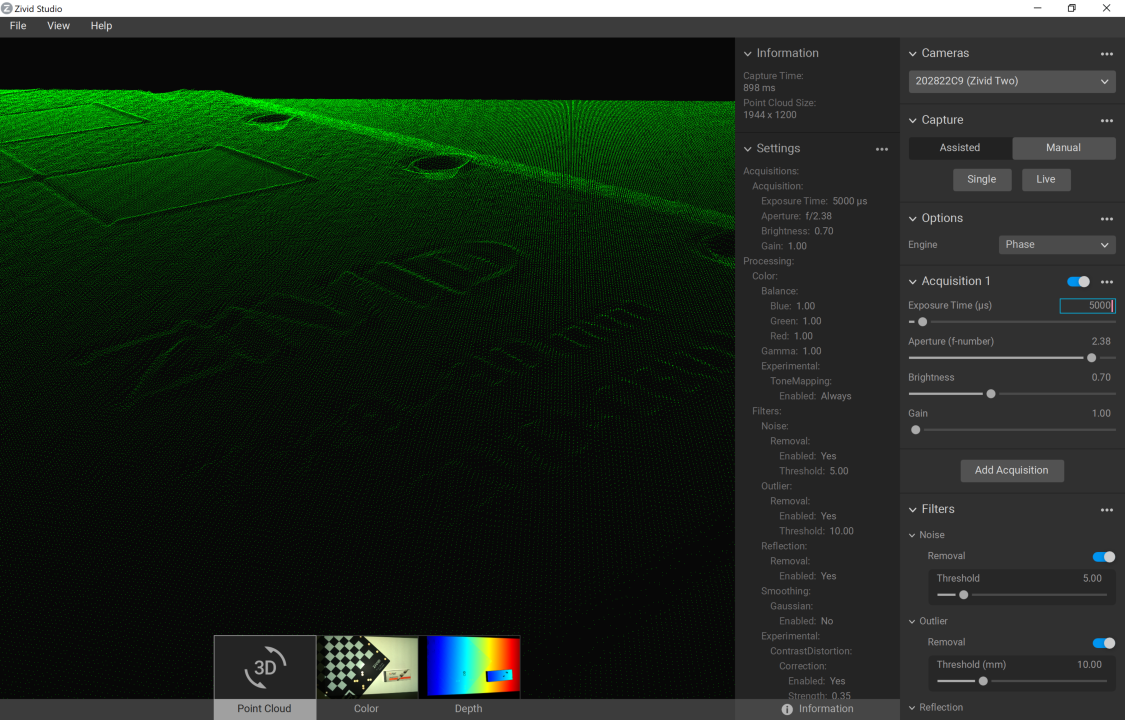
The figure below shows a color image out of focus and a resulting point cloud with visible contrast distortion artifacts. The color image is blurry because a low f-number (2.38) is used for the Aperture. The Contrast Distortion strength used is 0.35.
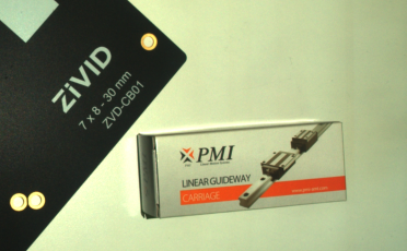
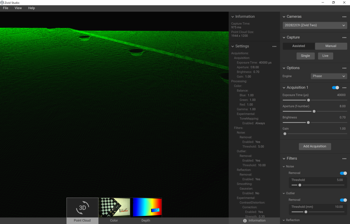
The Aperture is changed from 2.0 to 8.0 to remove the contrast distortion artifact, and this change is compensated with a longer Exposure Time. The result is a color image in focus and a point cloud without any contrast distortion artifacts, which can be seen in the figure below.
The point clouds used for this example are available for download for further inspection:
Check out how to set 3D processing settings, including filter settings, with Zivid SDK:
Zivid::Settings settings{
    Zivid::Settings::Color{ settings2D },

    Zivid::Settings::Engine::stripe,

    Zivid::Settings::RegionOfInterest::Box::Enabled::yes,
    Zivid::Settings::RegionOfInterest::Box::PointO{ 1000, 1000, 1000 },
    Zivid::Settings::RegionOfInterest::Box::PointA{ 1000, -1000, 1000 },
    Zivid::Settings::RegionOfInterest::Box::PointB{ -1000, 1000, 1000 },
    Zivid::Settings::RegionOfInterest::Box::Extents{ -1000, 1000 },

    Zivid::Settings::RegionOfInterest::Depth::Enabled::yes,
    Zivid::Settings::RegionOfInterest::Depth::Range{ 200, 2000 },

    Zivid::Settings::Processing::Filters::Cluster::Removal::Enabled::yes,
    Zivid::Settings::Processing::Filters::Cluster::Removal::MaxNeighborDistance{ 10 },
    Zivid::Settings::Processing::Filters::Cluster::Removal::MinArea{ 100 },

    Zivid::Settings::Processing::Filters::Hole::Repair::Enabled::yes,
    Zivid::Settings::Processing::Filters::Hole::Repair::HoleSize{ 0.2 },
    Zivid::Settings::Processing::Filters::Hole::Repair::Strictness{ 1 },

    Zivid::Settings::Processing::Filters::Noise::Removal::Enabled::yes,
    Zivid::Settings::Processing::Filters::Noise::Removal::Threshold{ 7.0 },

    Zivid::Settings::Processing::Filters::Noise::Suppression::Enabled::yes,
    Zivid::Settings::Processing::Filters::Noise::Repair::Enabled::yes,

    Zivid::Settings::Processing::Filters::Outlier::Removal::Enabled::yes,
    Zivid::Settings::Processing::Filters::Outlier::Removal::Threshold{ 5.0 },

    Zivid::Settings::Processing::Filters::Reflection::Removal::Enabled::yes,
    Zivid::Settings::Processing::Filters::Reflection::Removal::Mode::global,

    Zivid::Settings::Processing::Filters::Smoothing::Gaussian::Enabled::yes,
    Zivid::Settings::Processing::Filters::Smoothing::Gaussian::Sigma{ 1.5 },

    Zivid::Settings::Processing::Filters::Experimental::ContrastDistortion::Correction::Enabled::yes,
    Zivid::Settings::Processing::Filters::Experimental::ContrastDistortion::Correction::Strength{ 0.4 },

    Zivid::Settings::Processing::Filters::Experimental::ContrastDistortion::Removal::Enabled::no,
    Zivid::Settings::Processing::Filters::Experimental::ContrastDistortion::Removal::Threshold{ 0.5 },

    Zivid::Settings::Processing::Resampling::Mode::upsample2x2,

    Zivid::Settings::Diagnostics::Enabled::no,
};

setSamplingPixel(settings, camera);
std::cout << settings << std::endl;
var settings = new Zivid.NET.Settings()
{
    Engine = Zivid.NET.Settings.EngineOption.Stripe,

    RegionOfInterest =
    {
        Box = {
            Enabled = true,
            PointO = new Zivid.NET.PointXYZ{ x = 1000, y = 1000, z = 1000 },
            PointA = new Zivid.NET.PointXYZ{ x = 1000, y = -1000, z = 1000 },
            PointB = new Zivid.NET.PointXYZ{ x = -1000, y = 1000, z = 1000 },
            Extents = new Zivid.NET.Range<double>(-1000, 1000),
        },
        Depth =
        {
            Enabled = true,
            Range = new Zivid.NET.Range<double>(200, 2000),
        },
    },
    Processing =
    {
        Filters =
        {
            Cluster =
            {
                Removal = { Enabled = true, MaxNeighborDistance = 10, MinArea = 100}
            },
            Hole =
            {
                Repair = { Enabled = true, HoleSize = 0.2, Strictness = 1 },
            },
            Noise =
            {
                Removal = { Enabled = true, Threshold = 7.0 },
                Suppression = { Enabled = true },
                Repair = { Enabled = true },
            },
            Outlier =
            {
                Removal = { Enabled = true, Threshold = 5.0 },
            },
            Reflection =
            {
                Removal = { Enabled = true, Mode = ReflectionFilterModeOption.Global },
            },
            Smoothing =
            {
                Gaussian = { Enabled = true, Sigma = 1.5 },
            },
            Experimental =
            {
                ContrastDistortion =
                {
                    Correction = { Enabled = true, Strength = 0.4 },
                    Removal = { Enabled = true, Threshold = 0.5 },
                },
            },
        },
        Resampling = { Mode = Zivid.NET.Settings.ProcessingGroup.ResamplingGroup.ModeOption.Upsample2x2 },
    },
    Diagnostics = { Enabled = false },
};

settings.Color = settings2D;

SetSamplingPixel(ref settings, camera);
Console.WriteLine(settings);
settings = zivid.Settings()
settings.engine = zivid.Settings.Engine.stripe

settings.region_of_interest.box.enabled = True
settings.region_of_interest.box.point_o = [1000, 1000, 1000]
settings.region_of_interest.box.point_a = [1000, -1000, 1000]
settings.region_of_interest.box.point_b = [-1000, 1000, 1000]
settings.region_of_interest.box.extents = [-1000, 1000]

settings.region_of_interest.depth.enabled = True
settings.region_of_interest.depth.range = [200, 2000]

settings.processing.filters.cluster.removal.enabled = True
settings.processing.filters.cluster.removal.max_neighbor_distance = 10
settings.processing.filters.cluster.removal.min_area = 100

settings.processing.filters.hole.repair.enabled = True
settings.processing.filters.hole.repair.hole_size = 0.2
settings.processing.filters.hole.repair.strictness = 1

settings.processing.filters.noise.removal.enabled = True
settings.processing.filters.noise.removal.threshold = 7.0

settings.processing.filters.noise.suppression.enabled = True
settings.processing.filters.noise.repair.enabled = True

settings.processing.filters.outlier.removal.enabled = True
settings.processing.filters.outlier.removal.threshold = 5.0

settings.processing.filters.reflection.removal.enabled = True
settings.processing.filters.reflection.removal.mode = (
    zivid.Settings.Processing.Filters.Reflection.Removal.Mode.global_
)

settings.processing.filters.smoothing.gaussian.enabled = True
settings.processing.filters.smoothing.gaussian.sigma = 1.5

settings.processing.filters.experimental.contrast_distortion.correction.enabled = True
settings.processing.filters.experimental.contrast_distortion.correction.strength = 0.4

settings.processing.filters.experimental.contrast_distortion.removal.enabled = False
settings.processing.filters.experimental.contrast_distortion.removal.threshold = 0.5

settings.processing.resampling.mode = zivid.Settings.Processing.Resampling.Mode.upsample2x2

settings.diagnostics.enabled = False

settings.color = settings_2d

_set_sampling_pixel(settings, camera)
print(settings)
Further reading
Continue to Optimizing Color Image.
Version History
SDK |
Changes |
|---|---|
2.17.0 |
Added support for Zivid 3 XL250. |
2.9.0 |
Added sections for Cluster and Hole Filling filters, and updated the Gaussian section based on the new behavior introduced in 2.9.0. |
