Working Distance and Field-of-View
This page shows the field-of-view (FOV) diagrams and CAD datum reference for each Zivid camera model; use the FOV and imaging distance calculator to find the relation between distances and FOV for your camera.
Note
The FOV figures on this page represent the overlap between the 2D camera and the projector. This overlap varies by roughly up to a degree from unit to unit, due to unit-to-unit variation in optical alignment from assembly (see datasheet for the specified tolerance). The FOV figures, the calculator, and the CAD files are therefore all nominal, not exact for a specific unit.
Zivid 3
XL250

FOV CAD files
CAD model information
The datum reference of the Zivid 3 CAD models is at the center of the Ø5 positioning hole (B in the image below).

The Optical center is found relative to the datum reference.
Zivid 2+
MR130/M130
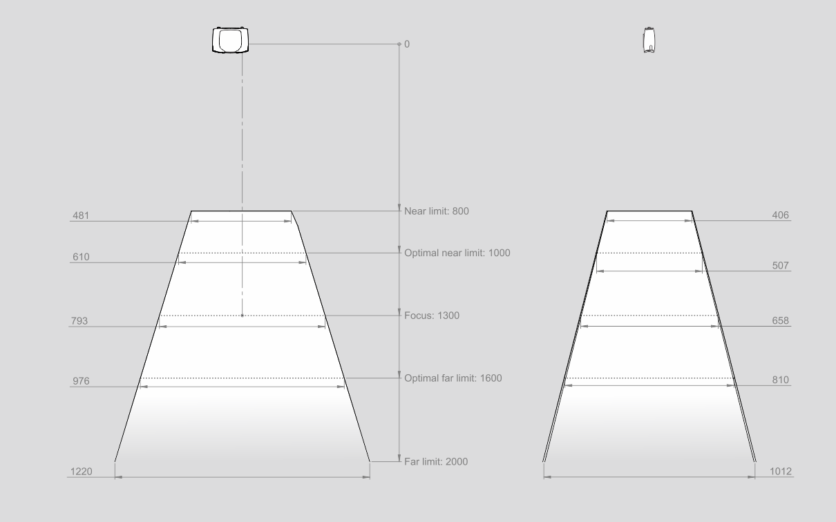
LR110/L110
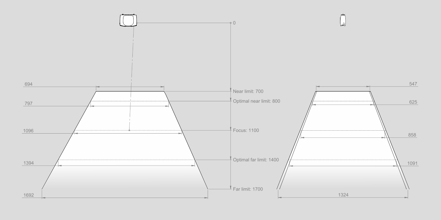
MR60/M60
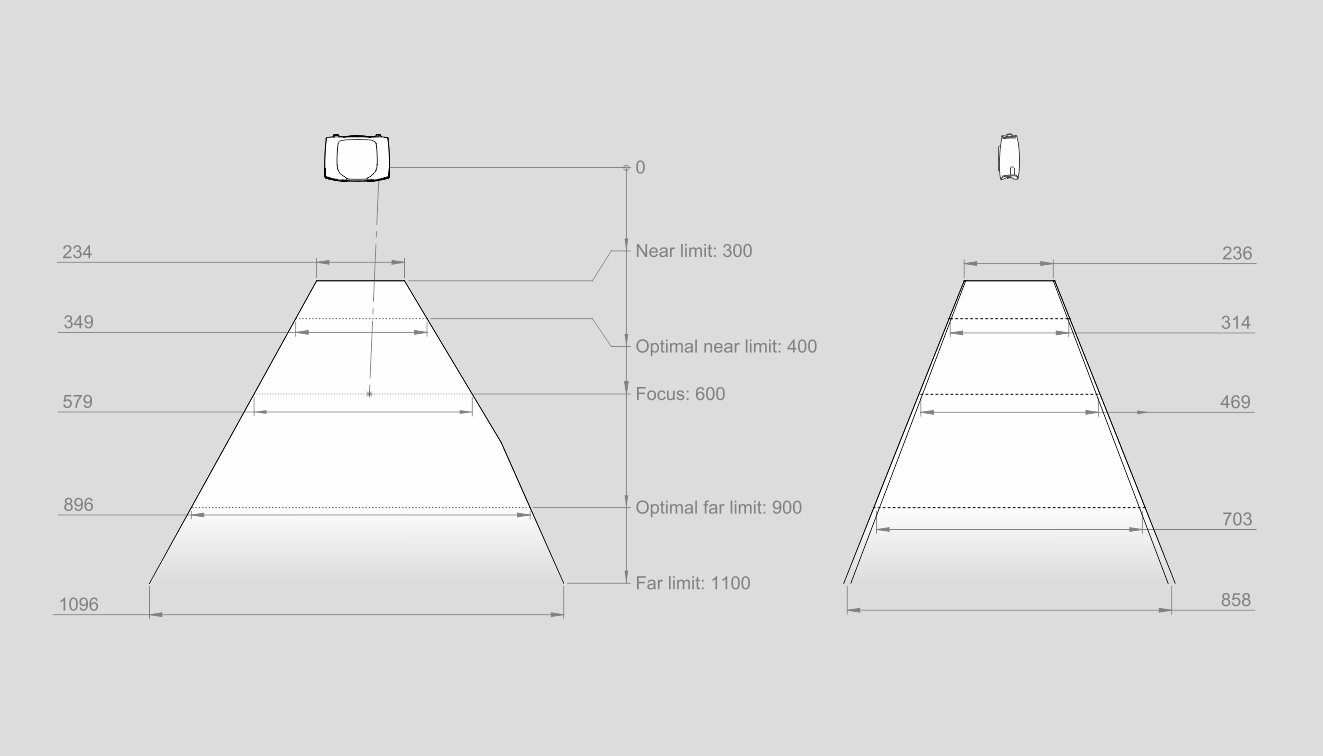
CAD model information
The datum reference of the Zivid 2+ CAD models is at the center of the Ø5 positioning hole (B in the image below).
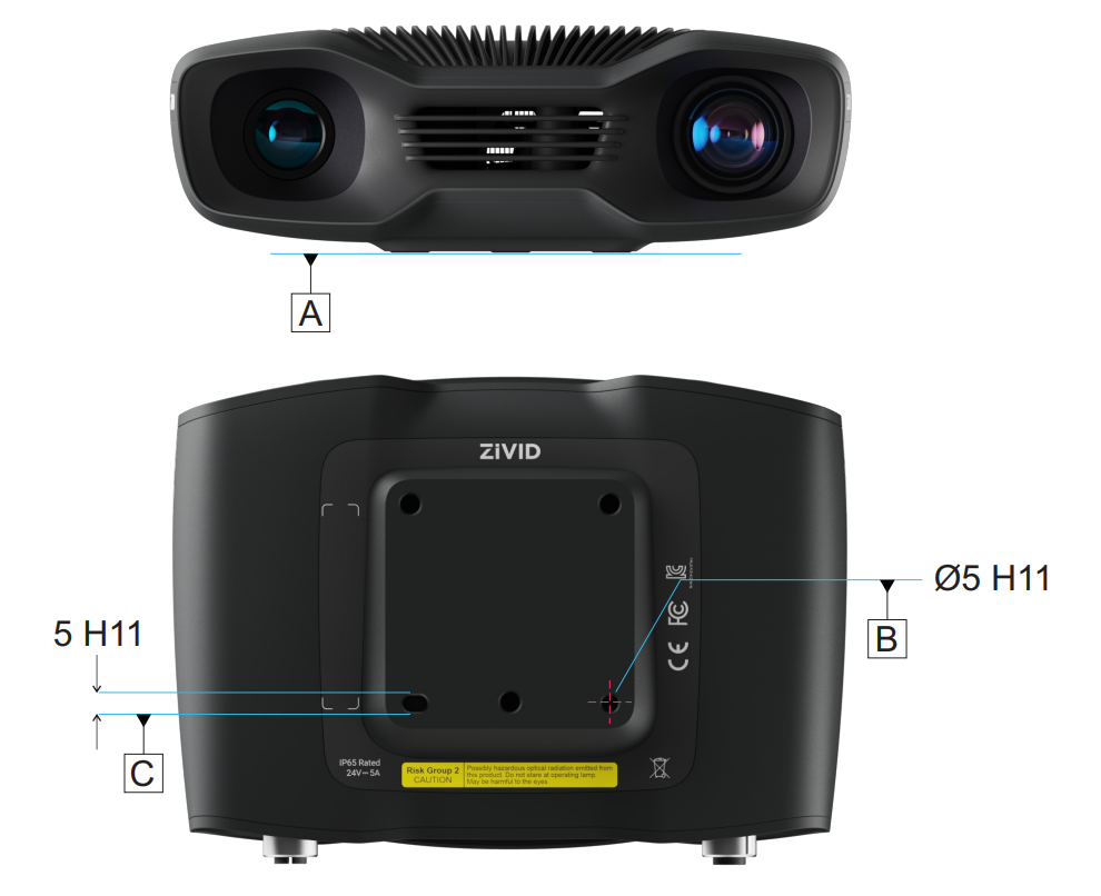
The Optical center is found relative to the datum reference.
Zivid 2
M70
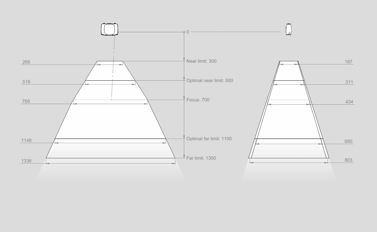
FOV CAD files
L100
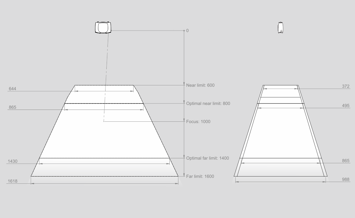
FOV CAD files
CAD model information
The datum reference of the Zivid 2 CAD models is at the center of the Ø5 positioning hole (B in the image below).
The Optical center is found relative to the datum reference.
Continue reading about the Mechanical Interface of Zivid cameras.
Version History
SDK |
Changes |
|---|---|
2.17.0 |
Added support for Zivid 3 XL250. |
2.14.0 |
Added support for Zivid 2+ MR130, LR110, and MR60. |
2.12.0 |
Zivid One+ has reached its End-of-Life and is no longer supported. |