Production Preparation Processes
We have several processes and tools within the Zivid SDK to help you set up your system and prepare it for production. The essential ones that we advise doing before deploying are:
warm-up
infield correction
hand-eye calibration
Using these processes, we want to imitate the production conditions to optimize the camera for working temperature, distance, and FOV. Other tools that can help you reduce the processing time during production and hence maximize your picking rate are:
downsampling
transforming and ROI box filtering
Robot Calibration
Before starting production, you should make sure your robot is well calibrated, demonstrating good positioning accuracy. For more information about robot kinematic calibration and robot mastering/zeroing, contact your robot supplier.
Warm-up
Allowing the Zivid 3D camera to warm up and reach thermal equilibrium can improve the overall accuracy and success of an application. This is recommended if the application requires tight tolerances, e.g., picking applications with < 5 mm tolerance per meter distance from the camera. A warmed-up camera will improve both infield correction and hand-eye calibration results.
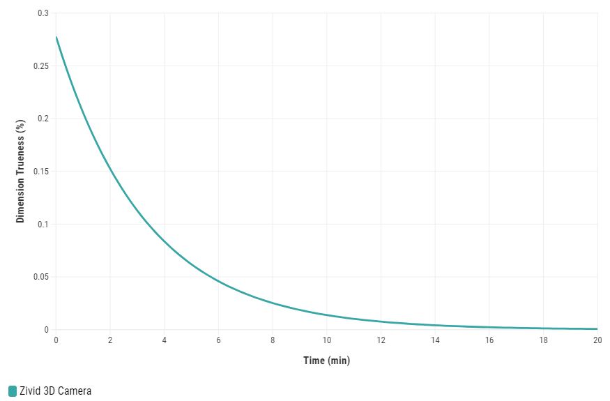
To warm up your camera, you can run our code sample, providing cycle time and path to your camera settings.
Sample: warmup.py
python /path/to/warmup.py --settings-path /path/to/settings.yml --capture-cycle 6.0
To understand better why warm-up is needed and how to perform it with SDK, read our Warm-up article.
Infield Correction
Infield correction is a maintenance tool designed to verify and correct the dimension trueness of Zivid cameras. The user can check the dimension trueness of the point cloud at different points in the field of view (FOV) and determine if it is acceptable for their application. If the verification shows the camera is not sufficiently accurate for the application, then a correction can be performed to increase the dimension trueness of the point cloud. The average dimension trueness error from multiple measurements is expected to be close to zero (<0.1%).
Why is this necessary?
Our cameras are made to withstand industrial working environments and continue to return quality point clouds. However, like most high precision electronic instruments, sometimes they might need a little adjustment to make sure they stay at their best performance. When a camera experiences substantial changes in its environment or heavy handling it could require a correction to work optimally in its new setting.
Read more about Infield Correction if this is your first time doing it.
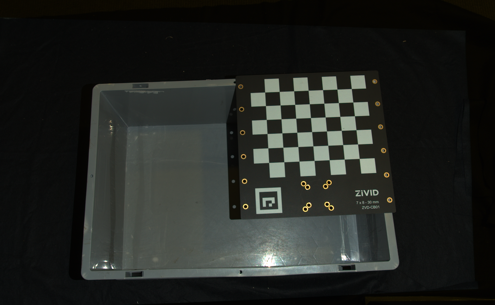
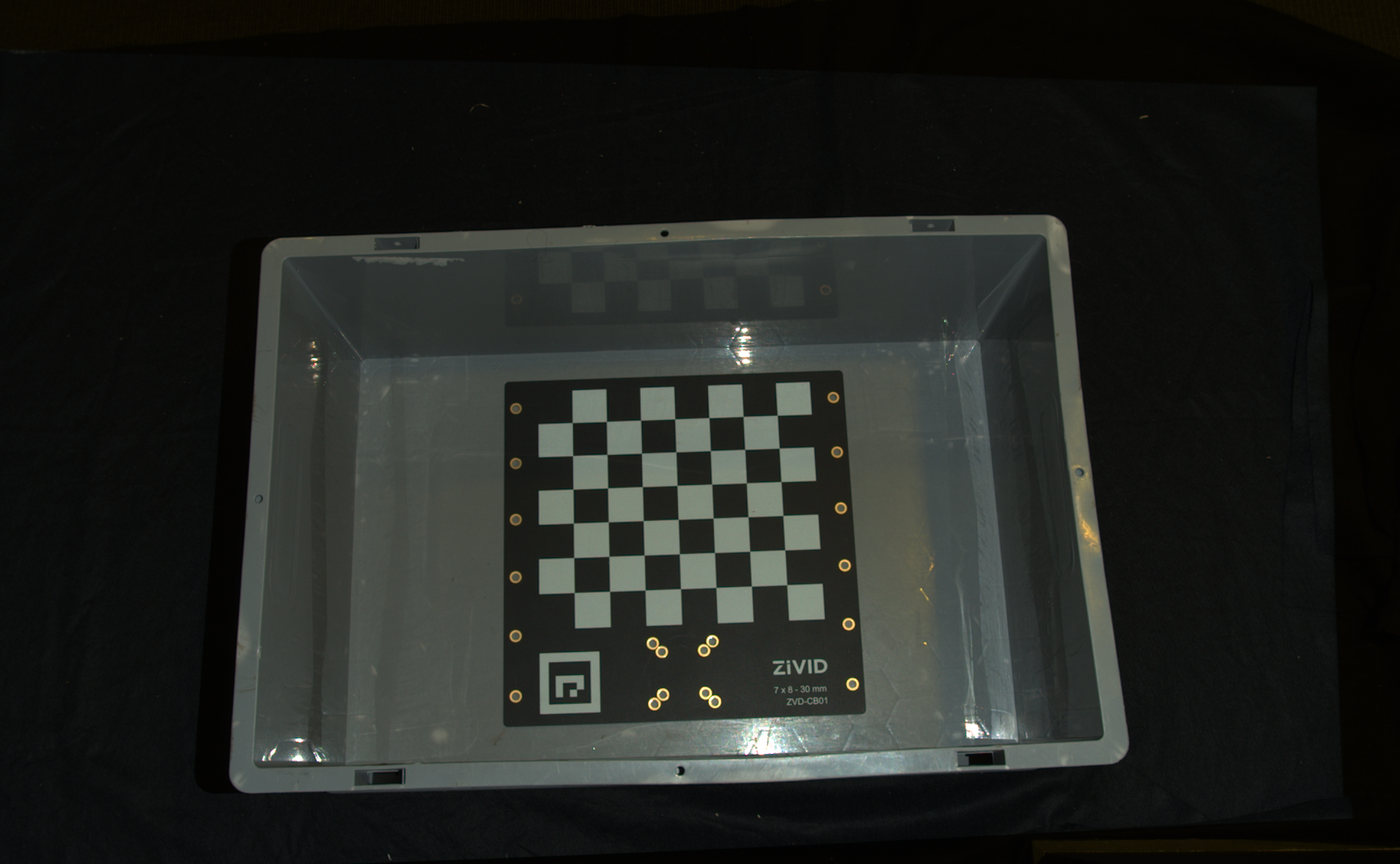
When running infield verification, ensure that the dimensional trueness is good at both the top and bottom of the bin. For on-arm applications, move the robot to the capture pose when doing infield verification. If the verification results are good, you don’t need to run infield correction.
|
|
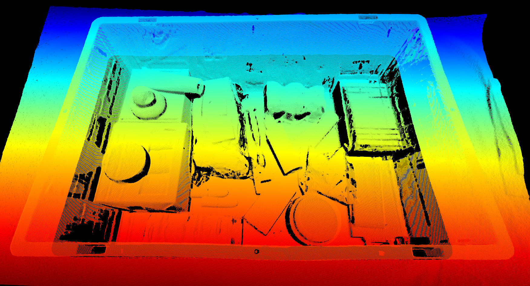
Calibration board at bin top for infield verification |
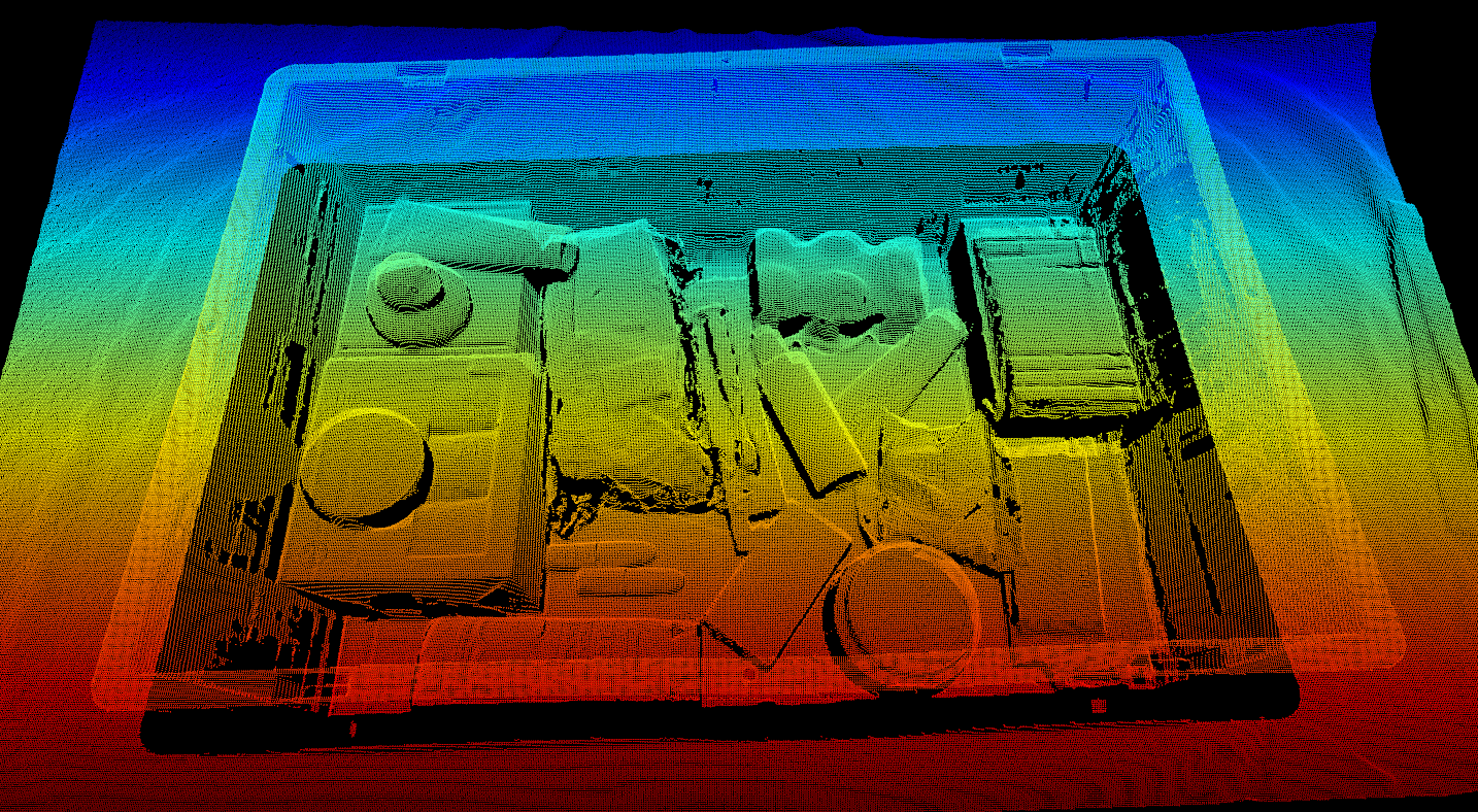
Calibration board at bin bottom for infield verification |
When infield correction is required, span the entire working volume for optimal results. This means placing the Zivid calibration board in multiple locations for a given distance and doing that at different distances while ensuring the entire board is in FOV. A couple of locations at the bottom and a couple at the top of the bin are sufficient for piece picking. Check Guidelines for Performing Infield Correction for more details.
To run infield verification and/or correction on a camera you can use:
Zivid Studio
CLI tool
SDK
Tip
If you are running Infield correction for the first time, we recommend using Zivid Studio.
Check out Running Infield Correction for step-by-step guide on running Infield correction.
Hand-Eye Calibration
The picking accuracy of a vision-guided robotic system depends on the combined accuracy of the camera, hand-eye calibration, machine vision software, and robot’s positioning. Robots are in general highly repeatable but not accurate. Temperature, joint friction, payload, and manufacturing tolerances are some of the factors that cause the robot to deviate from its preprogrammed positioning. However, robot pose accuracy can be improved by calibrating the robot itself, which is highly recommended for complex systems with multiple factors that affect the picking accuracy. If the robot loses the calibration, the picking accuracy will deteriorate. Repeating the calibration (robot and/or hand-eye) can compensate for such deteriorated performance. It is also necessary to repeat the hand-eye calibration after dismounting the camera from a fixed structure or a robot and mounting it back on.
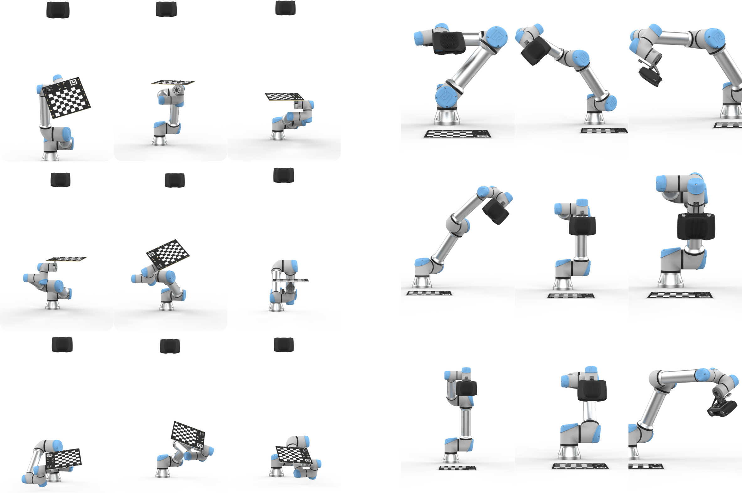
We have code samples that enable performing hand-eye calibration easily:
UR5 Robot + Python: Generate Dataset and perform Hand-Eye Calibration
Any Robot + RoboDK + Python: Generate Dataset and Perform Hand-Eye Calibration
Alternatively, computing hand-eye transform can be done using a CLI tool:
After completing hand-eye calibration, you may want to verify that the resulting transformation matrix is correct and within the accuracy requirements. We offer two options:
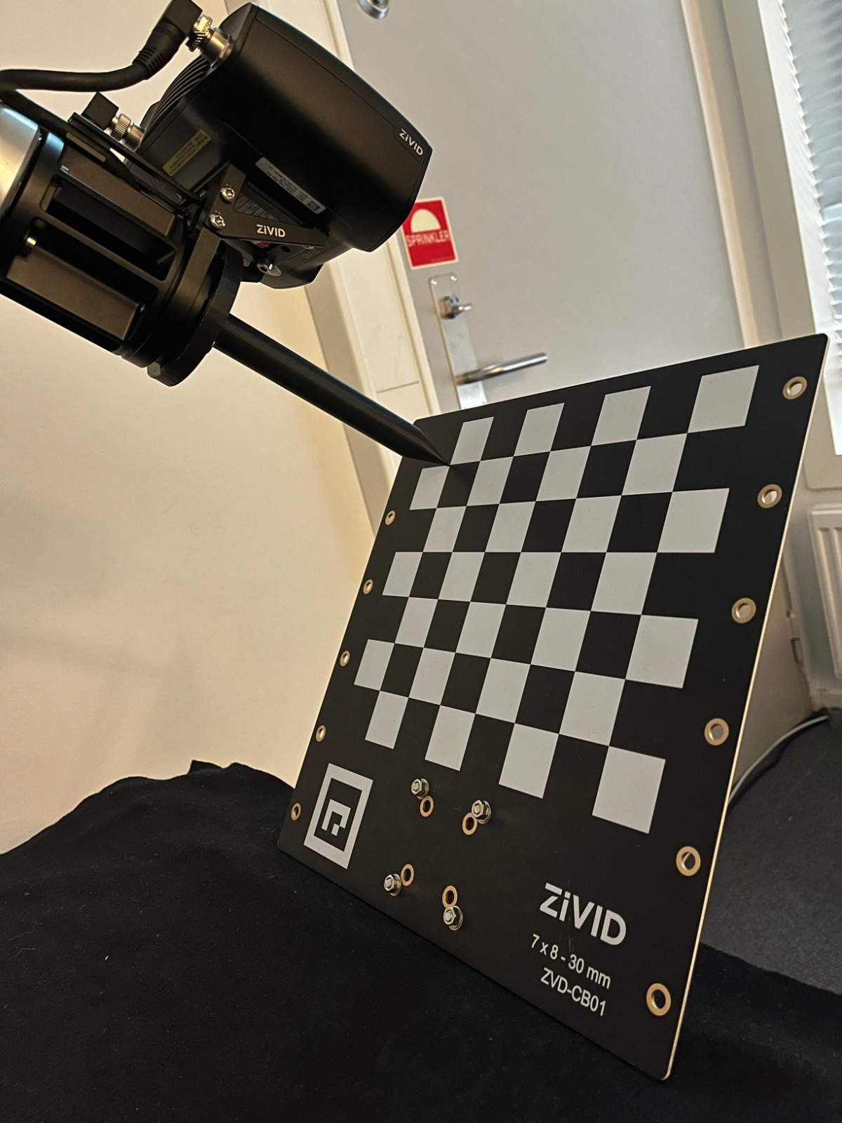
To learn more about the topic, check out Hand-Eye Calibration.
Color Balance
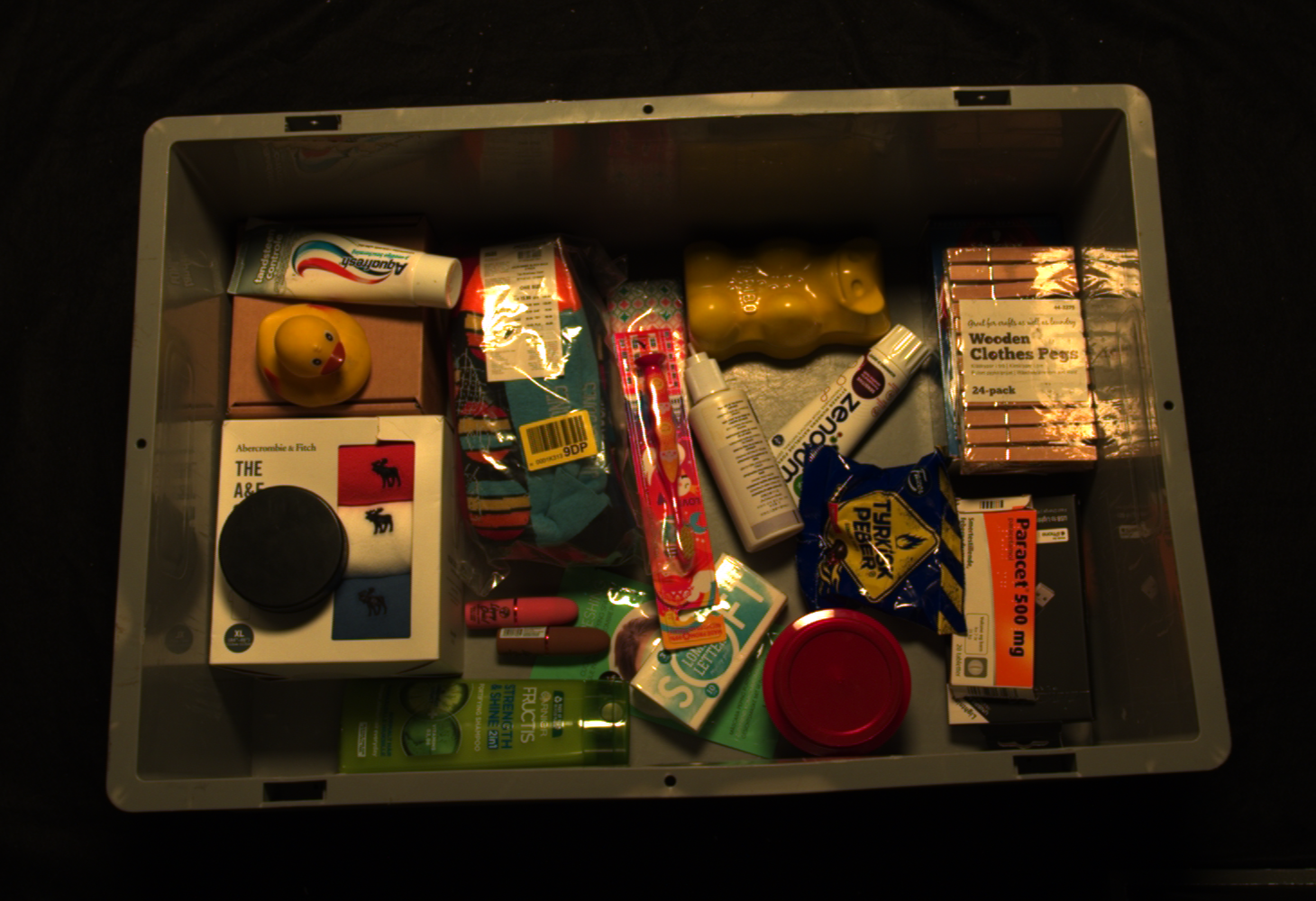
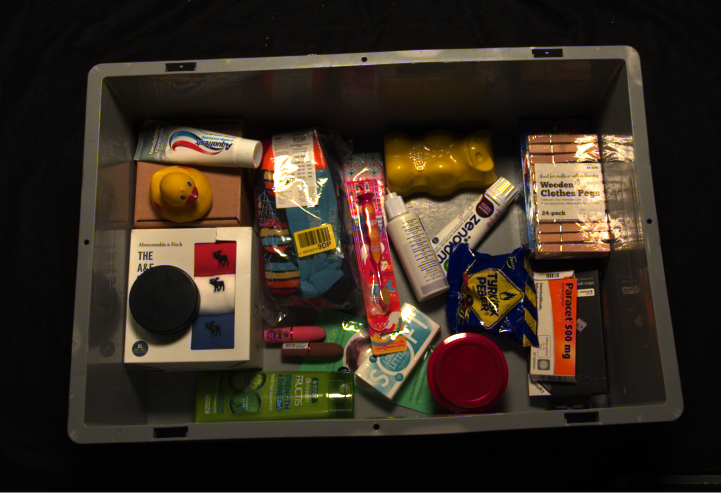
In the SDK, we have functionality for adjusting the color balance values for red, green, and blue color channels. Ambient light that is not perfectly white and/or is significantly strong will affect the RGB values of the color image. Run color balance on the camera if your application requires the correct RGB. This is especially the case if you are not using the Zivid camera projector to capture color images.
|
|
Point cloud before color balance |
Point cloud after color balance |
To balance the color of a 2D image, you can run our code sample, providing path to your 2D acquisition settings.
Sample: color_balance.py
python color_balance.py /path/to/settings.yml
As output, 2D acquisition settings with the new color balance gains are saved to file.
Check out our Adjusting Color Balance page for further explanation, how to perform it with SDK, and code sample walk-through.
Downsampling
Some applications do not require high-density point cloud data, for example, box detection by fitting a plane to the box surface. In addition, this amount of data is often too large for machine vision algorithms to process with the speed required by the application. It is such applications where point cloud downsampling comes into play.
Downsampling in point cloud context is the reduction in spatial resolution while keeping the same 3D representation. It is typically used to transform the data to a more manageable size and thus reduce the storage and processing requirements.
|
|
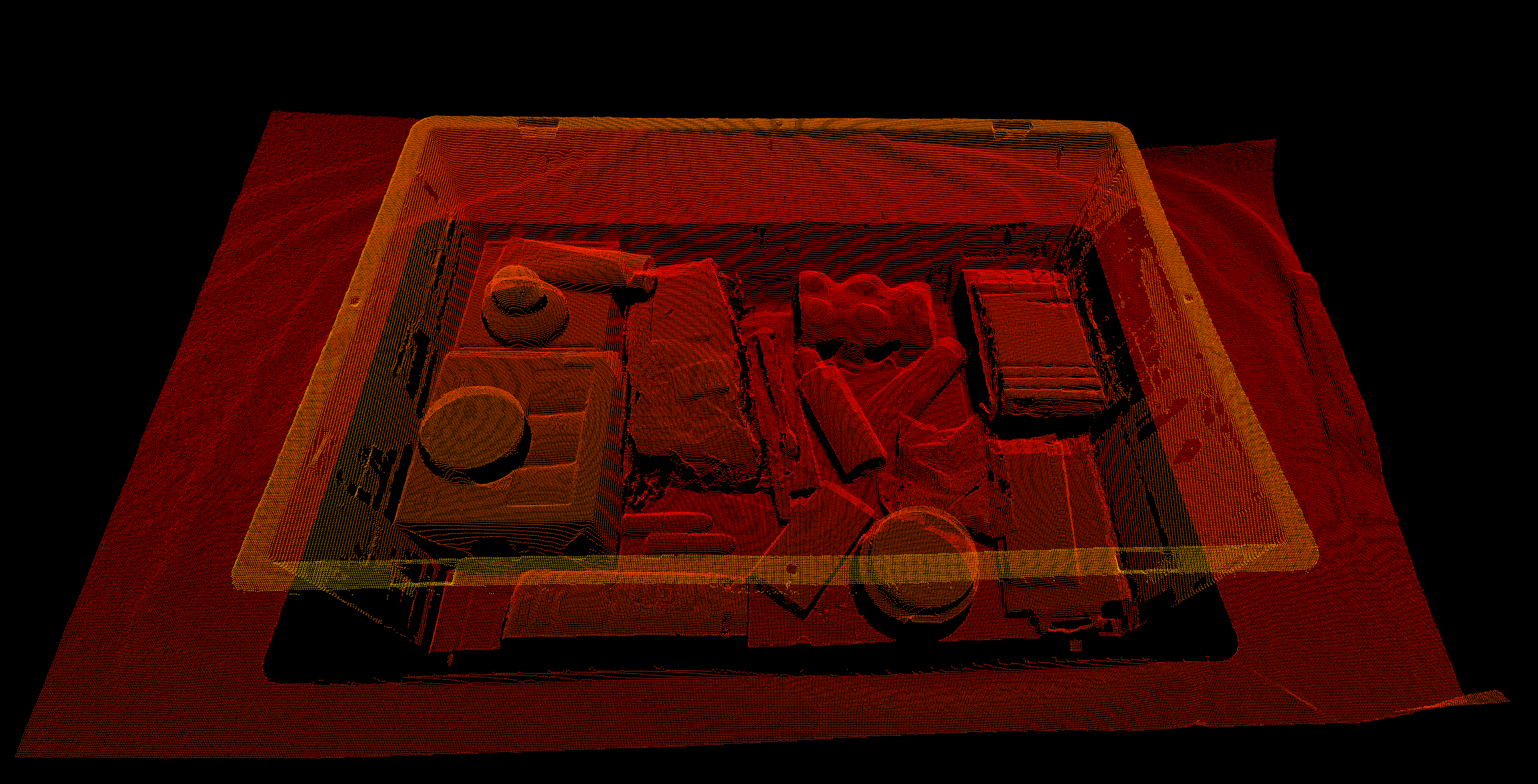
Point cloud before downsampling |
Point cloud after downsampling |
Downsampling can be done in-place, which modifies the current point cloud.
It is also possible to get the downsampled point cloud as a new point cloud instance, which does not alter the existing point cloud.
Zivid SDK supports the following downsampling rates: by2x2, by3x3, and by4x4, with the possibility to perform downsampling multiple times.
To downsample a point cloud, you can run our code sample, or you can skip it now, and do it as part of the next step of this tutorial.
Sample: downsample.py
python /path/to/downsample.py --zdf-path /path/to/file.zdf
If you don’t have a ZDF file, you can run the following code sample. It saves a Zivid point cloud captured with your settings to file.
Sample: capture_with_settings_from_yml
python /path/to/capture_with_settings_from_yml.py --settings-path /path/to/settings.yml
To read more about downsampling, go to Downsample.
ROI Box Filtering
The camera field of view is often larger than our Region of Interest (ROI), e.g., a bin. If we want to further reduce the number of data points used by the detection algorithm, we can set an ROI box around the bin and crop the point cloud based on it to get only the points of the bin contents. Reducing the number of data points will not decrease the capture time, as ROI filtering is a post-processing step. Nevertheless, it can speed up the object detection algorithm and hence reduce the total cycle time.
Tip
Smaller point clouds can make the detection faster and total picking cycle times shorter.
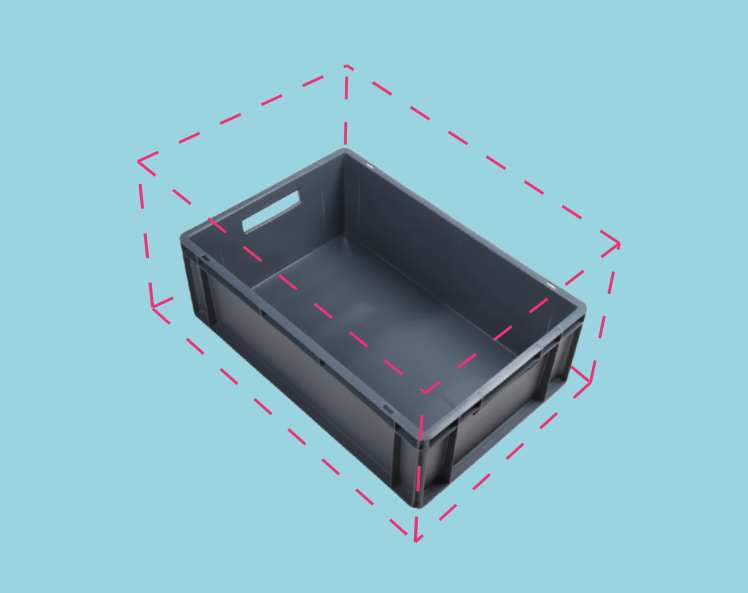
For an implementation example, check out ROI Box via Checkerboard. This tutorial demonstrates how to filter the point cloud using the Zivid calibration board based on a ROI box given relative to the checkerboard.
|
|
Downsampled point cloud before ROI cropping |
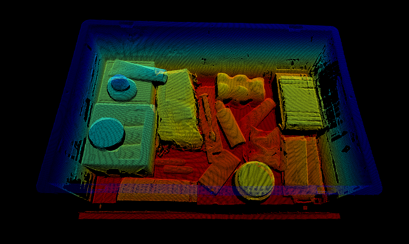
Downsampled point cloud after ROI cropping |
Congratulations! You have covered everything on the Zivid side to be ready to put your piece picking system into production. The following section is Maintenance which covers specific processes we advise carrying out to ensure that the piece picking cell is stable with minimum downtime.
