通过ArUco标记实现的ROI框过滤器
本教程演示如何过滤转换到基于与ArUco标记相关联的ROI框的ArUco标记坐标系的点云。这将过滤掉所有在料箱之外的点。
小技巧
Zivid calibration board 包含一个 ArUco 标记。
本教程使用了下图中展示的ArUco标记点云。
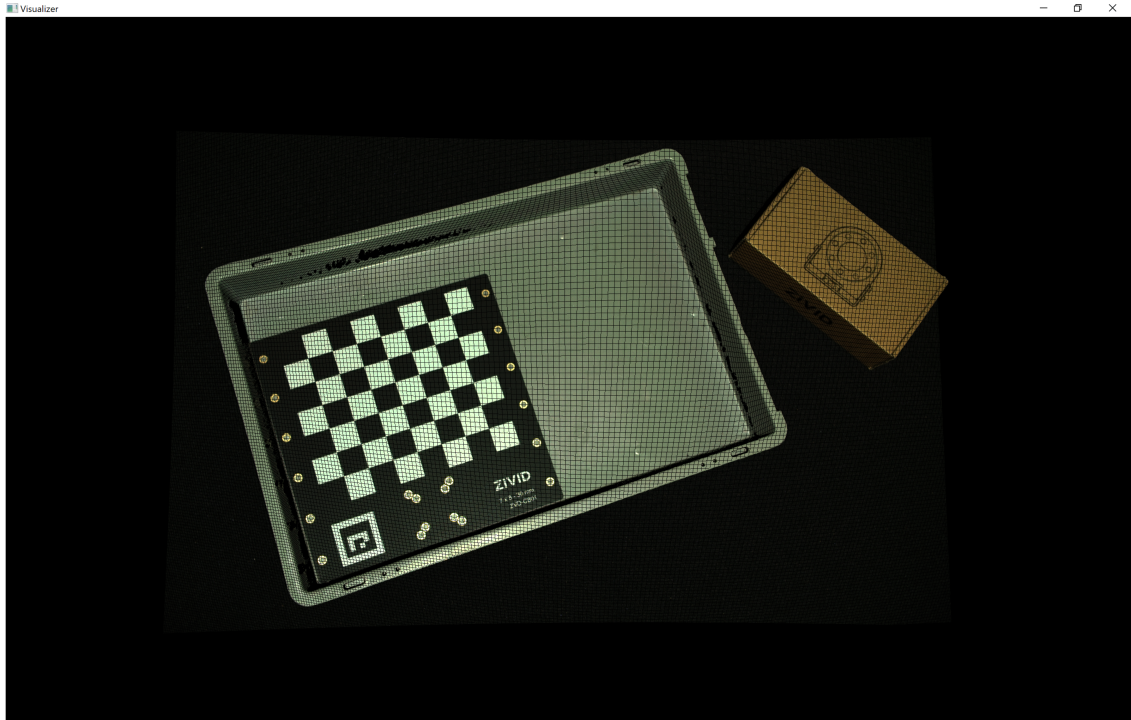
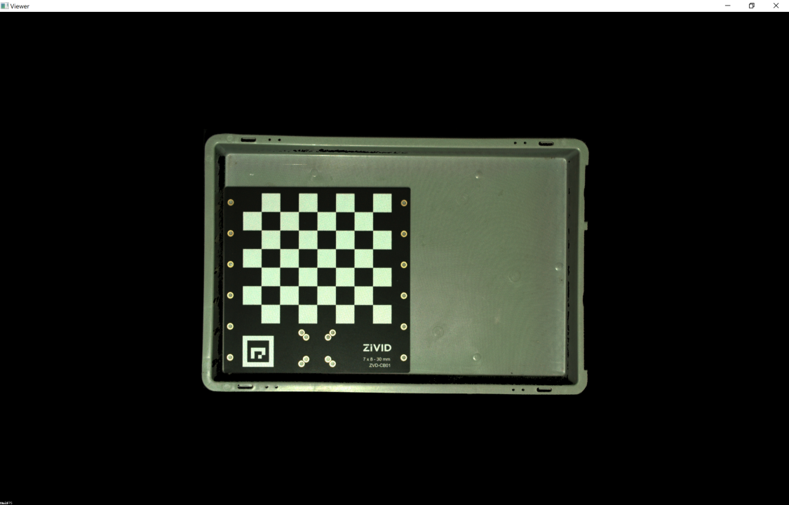
我们可以在Zivid Studio中打开 原始点云 并进行检查。
备注
原始点云在 Sample Data(示例数据) 中。
这里将略过关于转换点云的部分,这部分在 基于ArUco标记的坐标转换 已涵盖, 请转到 基于ROI框的过滤。
转换点云
首先,我们加载一个 ArUco 标记的点云。
由于我们使用的是OpenCV,因此需要将2D图像从点云转换为OpenCV图像格式。
然后我们将配置ArUco标记。

std::cout << "Configuring ArUco marker" << std::endl;
const auto markerDictionary = cv::aruco::getPredefinedDictionary(cv::aruco::DICT_4X4_100);
std::vector<int> markerIds;
std::vector<std::vector<cv::Point2f>> markerCorners;
cv::Ptr<cv::aruco::DetectorParameters> detectorParameters = cv::aruco::DetectorParameters::create();
detectorParameters->cornerRefinementMethod = cv::aruco::CORNER_REFINE_SUBPIX;
接下来在2D图像中检测ArUco标记。
然后估计ArUco标记的位姿。
将点云转换到ArUco标记坐标系。
提示
了解更多关于 位置、方向和坐标变换。
基于ROI框的过滤
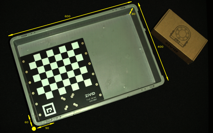
现在我们将定义ROI框的左下角相对于ArUco标记的位置,以及ROI框的大小。
std::cout << "Bottom-Left ROI Box corner:" << std::endl;
const int roiBoxBottomLeftCornerX = 60; // Positive is "South"
const int roiBoxBottomLeftCornerY = 90; // Positive is "West"
const int roiBoxBottomLeftCornerZ = 15; // Positive is "Down"
std::cout << "X: " << roiBoxBottomLeftCornerX << std::endl
          << "Y: " << roiBoxBottomLeftCornerY << std::endl
          << "Z: " << roiBoxBottomLeftCornerZ << std::endl;
std::cout << "ROI Box size:" << std::endl;
const int roiBoxLength = 600;
const int roiBoxWidth = 400;
const int roiBoxHeight = 80;
std::cout << "Length: " << roiBoxLength << std::endl
          << "Width: " << roiBoxWidth << std::endl
          << "Height: " << roiBoxHeight << std::endl;
现在我们根据ROI框的大小和位置过滤点云。这是通过使 用 PCL 库实现的。
std::cout << "Filtering the point cloud based on ROI Box" << std::endl;
const boost::shared_ptr<pcl::PointCloud<pcl::PointXYZRGB>> roiPointCloudPCL = roiBoxPointCloud(
    pointCloud,
    roiBoxBottomLeftCornerX,
    roiBoxBottomLeftCornerY,
    roiBoxBottomLeftCornerZ,
    roiBoxLength,
    roiBoxWidth,
    roiBoxHeight);
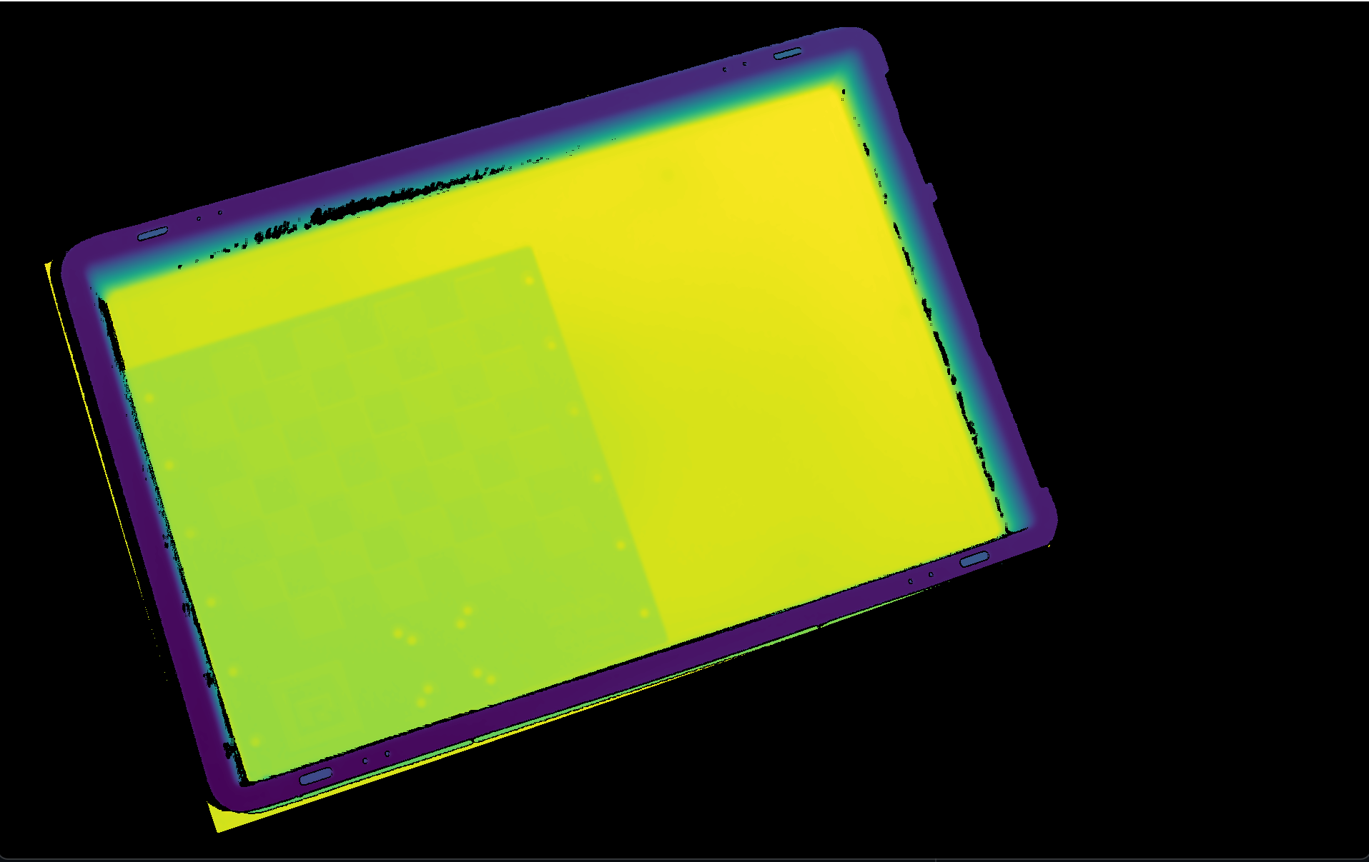
最后可视化经过转换和过滤的点云。
然后,我们将显示转换和过滤后的点云的深度图。