Mechanical Considerations for Robot Mounting
Introduction
This article aims to assist you in making the right decisions regarding purchasing or designing, integrating, and installing accessories and equipment for robot mounting.
It summarizes potential unwanted situations that may occur with on-arm mounted camera systems and provides guidelines and precautions to reduce the chances of these situations. It presents mechanical considerations and suggestions on design criteria to address particular challenges and minimize undesirable behavior.
The article shares our thoughts on this topic and highlights what we care about when designing our accessories.
Cable Entanglement
If camera cables become entangled, a force can be exerted on the connectors, damaging the connectors. In the worst case, the connectors will break off the internal PCB, significantly damaging the camera.
A cyclic dynamic load can affect the hand-eye calibration and loosen the on-arm mount screws. Such disturbance inflicting strain over time can also damage the connectors due to material fatigue.
Therefore, it is important to use a low footprint, on-arm mount with strain relief and a Cable Management System (CMS) to minimize the risk of cable entanglement.
Mount
A mount for attaching the camera to industrial and collaborative robots is a crucial piece of equipment for robot-mounting. The most important requirements for an on-arm mount are described as follows.
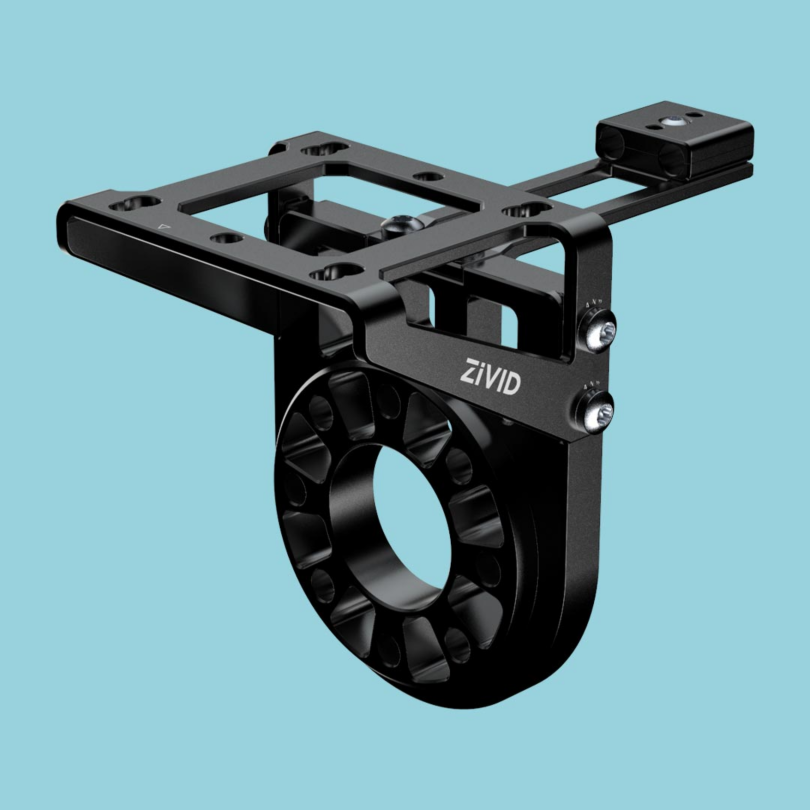
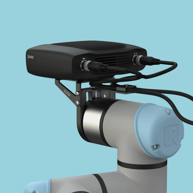
Sturdiness
The mount should be rigid, robust, and long-lasting. Robot movement must not cause the mount to vibrate or shift in any way. The same is true for all connections where screws hold the components together. Otherwise, the camera could still be moving when the robot stops, and motion during capture results in poor point clouds.
Lightweight
The mount should be lightweight and designed to have a low impact on the carrying capacity of the robot arm. This is especially important for collaborative robots and miniature industrial robots. Lightweight mounts allow using heavier tools and grippers and getting the most payload possible from the system.
Low Profile
The mount should be low enough to minimize the risk of collision and yet high enough to reduce the risk of having the gripper in the camera FOV. It should be compact and occupy a relatively small volume.
Modularity
The mount should fit multiple camera models because one might want to swap a camera for a newer or a different model. A modular mount design with multiple interchangeable camera brackets, each made to fit one camera model, is a good solution for this. Modularity also enables replacing the camera without complete disassembly.
Integrated Cable Management
It is beneficial if the mount has a strain relief on the back side of the camera, protecting the connectors in case of cable entanglement. The strain relief can be installed at the back or to either side, allowing for adaptability to each unique mounting scenario.
Occlusion Prevention
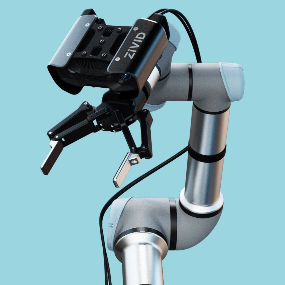
The mount should ensure the gripper does not occlude the camera view. Since there are many grippers available, one option is to have a modular mount with multiple camera brackets (e.g., flat and tilted) that one would choose based on the application.
Flexibility and Collision Prevention
The mount should have a low profile to reduce the risk of collision with other objects and provide a suitable gripper and robot arm clearance. The camera should stay clear of large grippers and gain headroom for challenging robot movement, thus preventing self-collision. For some applications, it is suitable to have the camera looking more towards the gripper, potentially reducing the required robot motion. A practical solution to meet different requirements is modular mounting with extenders that enables flexible configuration with multiple mounting poses.
Adaptability
The mount should support various robots from different vendors. Since there are multiple mechanical interface standards, one solution is a modular mount with adapter variants for different robot standards. Simplicity in adapting the mount to be compatible with a new robot is also beneficial, and ease of customization is another benefit of modular design.
User-friendliness
The mount should be designed with ease of assembly considerations in mind. The installation procedure should be intuitive and simple.
Recommendation
We recommend using Zivid On-Arm Mount since it meets all the above requirements.
Cable Management System
Cable Management System (CMS) is essential for robot-mounted applications because it minimizes the risk of cable entanglement. Having a cable retraction system for multi-axis robots is beneficial to prevent unwanted cable loops.
Recommendation
We recommend finding a specialist for CMS to help you choose the right one for your robot and application, e.g., Igus Cable Management Solutions.
Strain Relief
Strain relief is a fixture for cables that relieves the stress from the cable connections themselves to prevent them from breaking. It is usually located near the base of the connector, where the connector meets the cable. The strain relief protects the camera connectors if the cables get entangled by minimizing the risk of force being exerted directly on the cable connectors, physically damaging them. The strain relief component will help channel the unwanted force coming from entangled cables into the robot arm, giving it a chance to stop movement. Without the strain relief, the force is channeled via connectors and the camera.
What is a good strain relief?
The strain relief should be flexible to a certain degree because it should absorb some force if the cable gets entangled. If the strain relief is entirely rigid, the cable will get damaged before the robot stops. On the other hand, if it is too flexible, the robot will get the signal to stop too late.
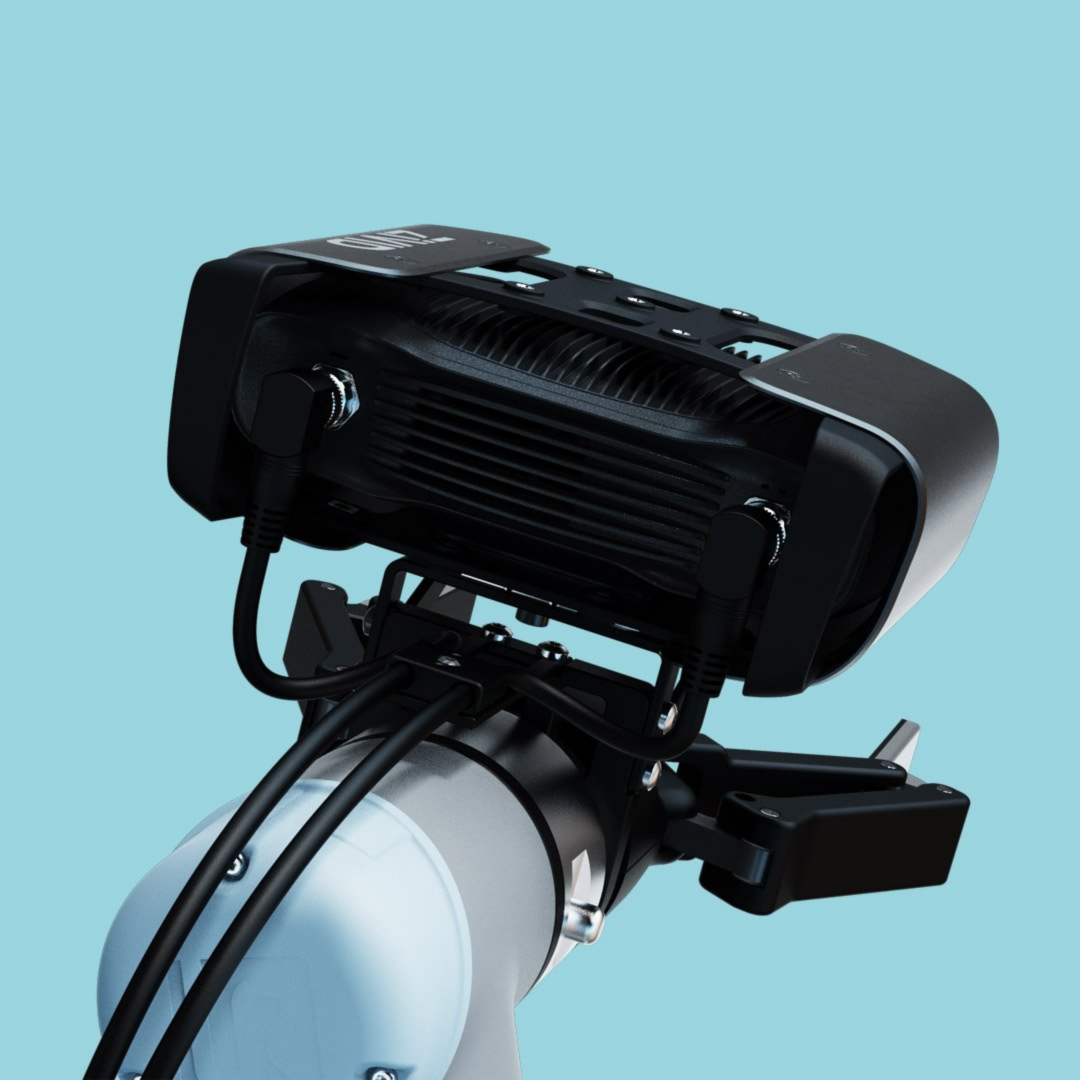
Recommendation
We recommend using Zivid On-Arm Mount, which comes with a strain relief component installed on the backside of the camera bracket. We also recommend an additional strain relief on the PC side to prevent the connectors or ports from getting damaged.
Integration of Strain Relief and Cable Management System
It is important to integrate the strain relief with the CMS properly.
The strain relief on the Zivid On-Arm Mount is typically located right behind the camera to minimize the cable length between it and the strain relief. For that reason, we recommend using a CMS that outputs the cables above the robot flange, thus also minimizing the cable length between the strain relief and the CMS.
An alternative solution is for the CMS and strain relief to meet on the side of the robot flange. In that case, the strain relief can be installed on the side of the on-arm mount. The Zivid On-Arm Mount supports this also.
Cables
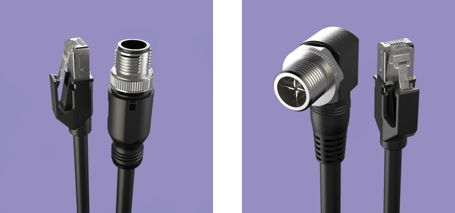
The cables must be specially designed for machine vision and robotics applications, meet flexibility and robustness requirements and be tested for twisting, bending, and pull force. It is common to need to provide mechanical reliability test reports for cables.
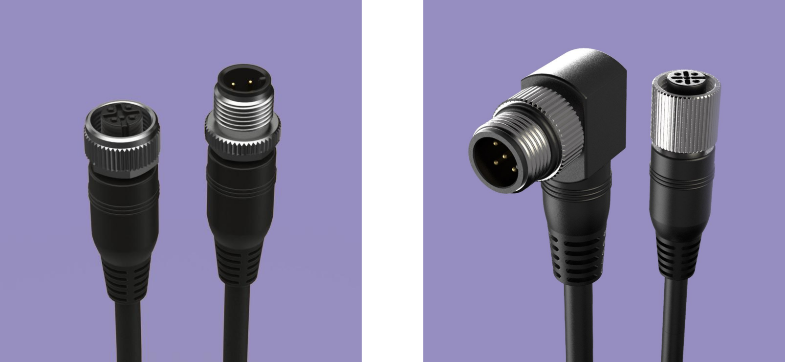
The cables are exposed to substantial motion since they are robot-mounted. In addition, the cables are often bent and twisted to ensure fixing to strain relief. Therefore, the cables need to have a sufficiently low static and dynamic radius, which are the parameters that describe the cable flexibility.
The cables must also be durable since they are exposed to various forces and surface friction during the motion. For the same reason, the cable connectors must be robust and industrial grade.
The cable lengths should be appropriate for the application, and it is handy to have different options. Some miniature robots need only 3 m long cables, while some of the larger robots, especially if installed on linear rails, may require cables up to 50 m in length.
It is beneficial to have both straight and angled 90-degree cables. This allows selecting either angled or straight connectors depending on the application and the type of strain relief and cable management system used. The cables also need to be compliant with Safety and EMC emission and immunity standards.
Recommendation
We recommend using Zivid cables because they are designed based on the above considerations. More info is available at Zivid Ethernet cables and Zivid Power Supply and Cables
Protective Housing
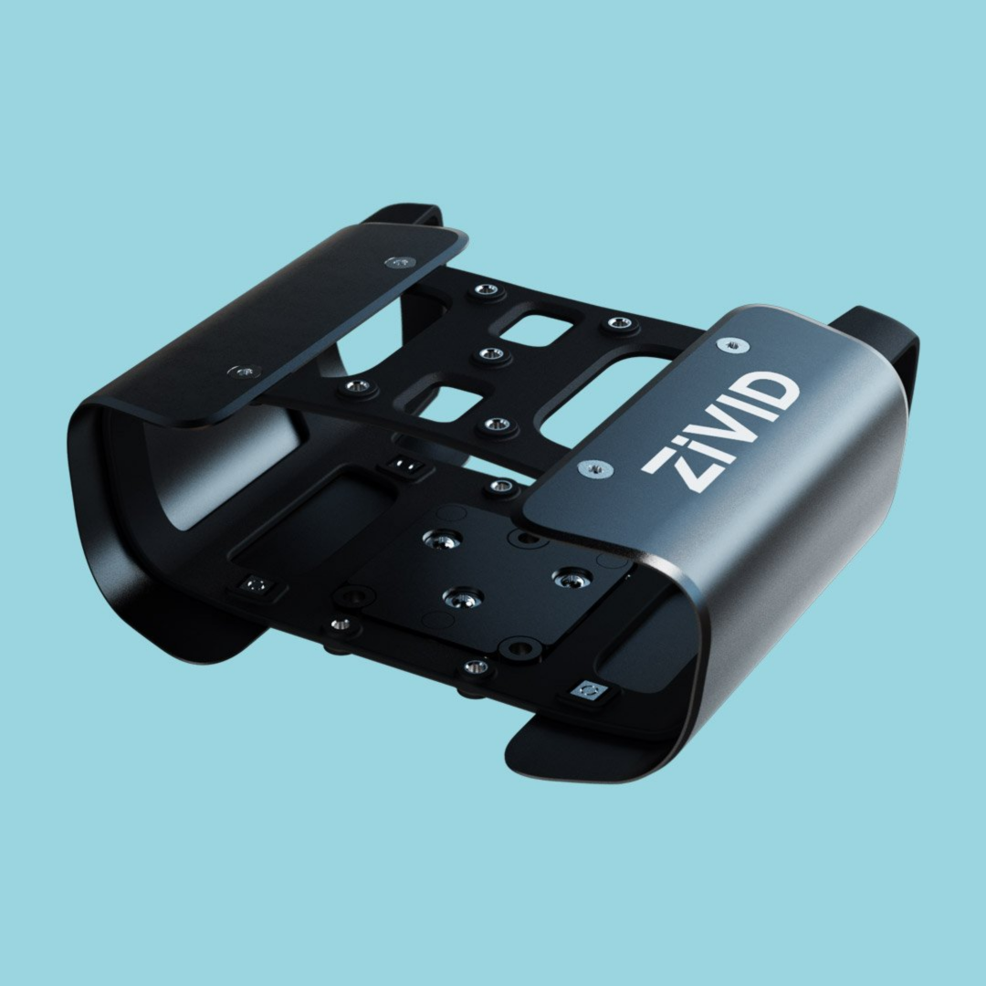
Protective housing for the camera needs to be designed and tested for optimal protection with minimal added weight and physical footprint.
Collisions happen, so it is better to absorb the shock rather than let it directly impact the camera and the robot. Featuring a built-in shock absorption in the camera base and choosing suitable material decreases the likelihood of damaging the camera in case of accidents.
The housing should integrate a cable protection system to reduce the probability of damaging cable connectors. It is beneficial to have a mounting fixture for additional equipment when needed.
The protective housing should also be compatible and integrate well with the camera mount.
Recommendation
We recommend using Zivid Two Protective Housing because it meets all the requirements mentioned above. For design recommendations on a complete enclosure with glass on the front side, check out Using Zivid Inside Protective Housing With Glass Window.
Installation
When installing any equipment on the robot (CMS, mounts, strain relief, protective housing), following instructions for recommended screw types, screw depth, and specified torque values for fastening screws is essential.
For additional safety to prevent screws from getting loose, we recommend using Loctite (purple or blue) and Nordlock washers. Regular flat washers will not help with vibrations but will help ensure the correct depth for screws entering a particular component.