Calibration
In this section, we will discuss multi-camera calibration.
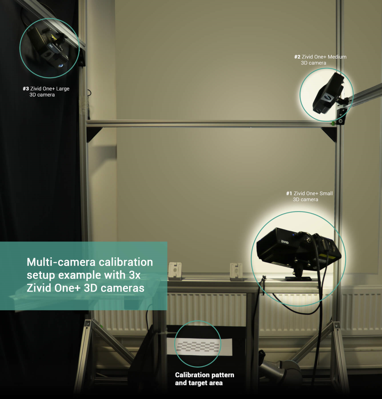
Set up cameras in different positions
For optimal performance, cameras should be mounted on a rigid structure. What matters is the rigidness of the structure that holds the cameras in their relative position. For demonstration purposes, tripods can be used, but note that re-calibration is required if cameras are moved out of their calibrated position.
In this article, we will focus on a simple two-camera setup.
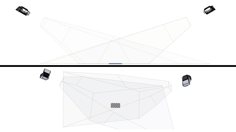
Place calibration object in view of cameras
There are a few considerations to make.
The entire calibration object must be visible from every camera.
We must get good quality data of the calibration object.
Further considerations on the placement of calibration plate (checkerboard)
:color: light
Consider the case where we want to place cameras at 180 degrees from each other. In other words, the cameras face each other. If we place the calibration object in the middle of the FOV we get the following scenario:
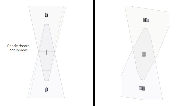
Fortunately, it is possible to reduce the angle limitation by moving the calibration object to one side of the FOV. This way one can still have the calibration object in view, even though the calibration object is aligned with the ZY-plane of both cameras (180 degrees scenario).
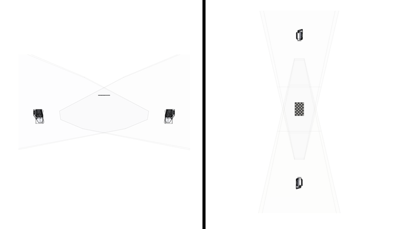
In practice, the checkerboard might not be detected even though it is in view. At such steep angles fewer pixels cover the checkerboard, thus it will have a poorer resolution. Thus, in practice, the limitation may be < 180 degrees.
We can extend this concept to more than two cameras. Consider the following use case:
Three cameras
120 degrees angle from each other
Mounted vertically (share YZ-plane)
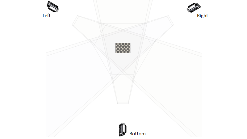
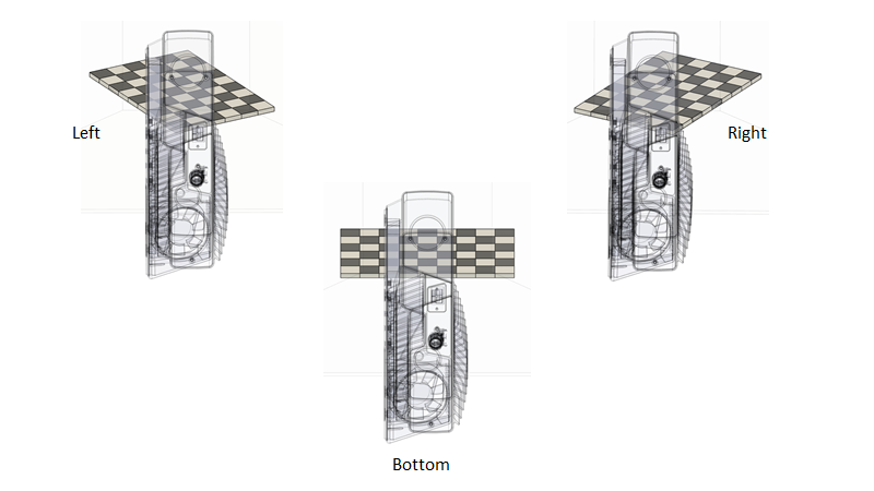
In this case the checkerboards have an angle that makes it possible to perform calibration.
Now let’s assume we tilt all the cameras horizontally in order to have a larger horizontal FOV.
Three cameras
120 degrees angle from each other
Mounted horizontally (share XZ-plane)
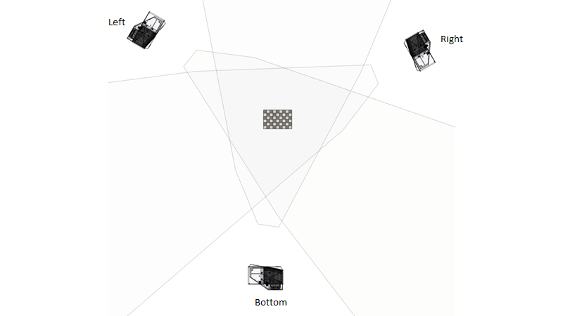
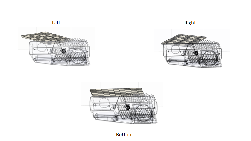
The FOV ratio forces us to move the calibration object closer to the common plane. Thus, the angle between the cameras and the calibration object is steeper. If the calibration cannot be performed because the resolution of the checkerboard is too low, or the point cloud quality is not good enough, then we turn to Multi-step calibration.
Calibration object must be visible in overlapping FOV
Currently, Zivid uses a calibration plate. It is a checkerboard that you can buy from the Zivid WebShop or print yourselves (see Calibration Object for more information). This object can only be viewed from one side, which imposes a limitation that is covered in How to Optimize the Placement of the Calibration Object.
We must get good quality data of the calibration object
To capture a good point cloud we first have to control the environment. The two most important considerations are to:
Have the calibration object in the optimal range of the cameras (see Working Distance and Camera Positioning for more details).
Limit the amount of ambient light (see Dealing with Strong Ambient Light for more details).
Check out How To Get Good Quality Data On Zivid Calibration Board.
Execute calibration
Calibration itself simply involves running our calibration software.
Tip
It is recommended to Warm-up the camera and run Infield Correction before running multi-camera calibration. To further reduce the impact of temperature dependent performance factors, enable Thermal Stabilization.
Capture point clouds of calibration object with all cameras.
Perform calibration.
Output Transformation Matrices.
This is all covered by the Multi-camera calibration sample application, which is described in detail in the Multi-camera calibration programming tutorial.
Now you can learn how to utilize the multi-camera calibration output to stitch the point clouds. Alternatively, learn about the theory behind multi-camera calibration.