Hand-Eye Calibration Solution
The previous part of this tutorial presented the problem that the hand-eye calibration needs to solve. This tutorial describes the background idea for a solution. The core idea is the same for eye-to-hand systems and eye-in-hand systems. Therefore, we first provide a detailed solution for the eye-to-hand configuration. Then, we point out the differences in the eye-in-hand configuration.
Note
You don’t need an end-of-arm tooling, or to know its pose (if you have one attached) to do the hand-eye calibration. The Tool Center Point (TCP) value does not affect the hand-eye calibration result. In this article and later tutorials, the term end-effector refers to the tool flange (last link of the robot).
How to solve the hand-eye calibration?
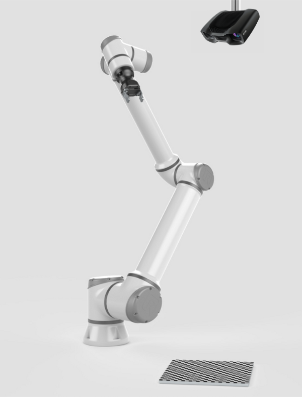
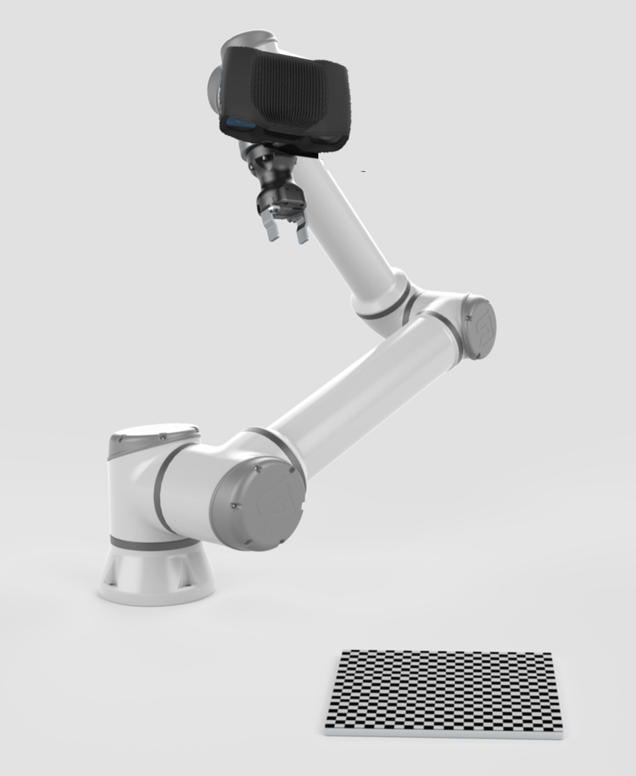
The first step is choosing a calibration object, e.g. a checkerboard. Zivid calibration objects (checkerboards and ArUco markers) will be covered in the next part of this tutorial. |
|
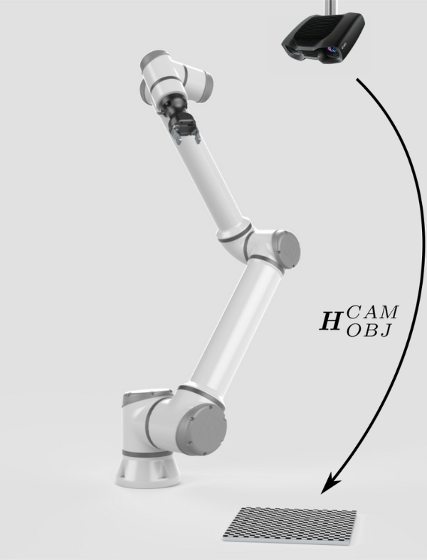
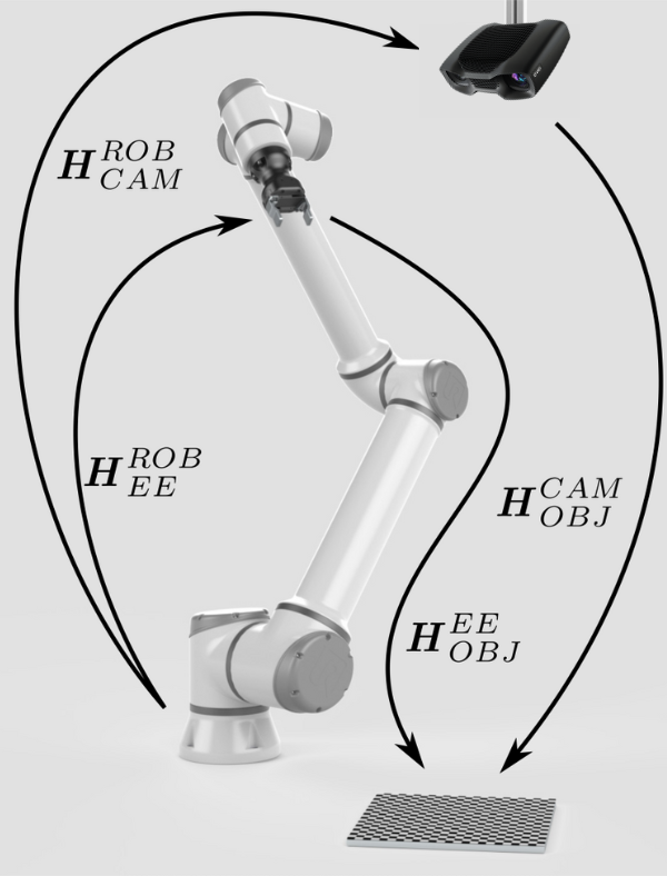
The calibration object is of known geometry. Thus, it can be detected from the camera image. Further, its pose relative to the camera (\(H^{CAM}_{OBJ}\)) can be estimated. |
|
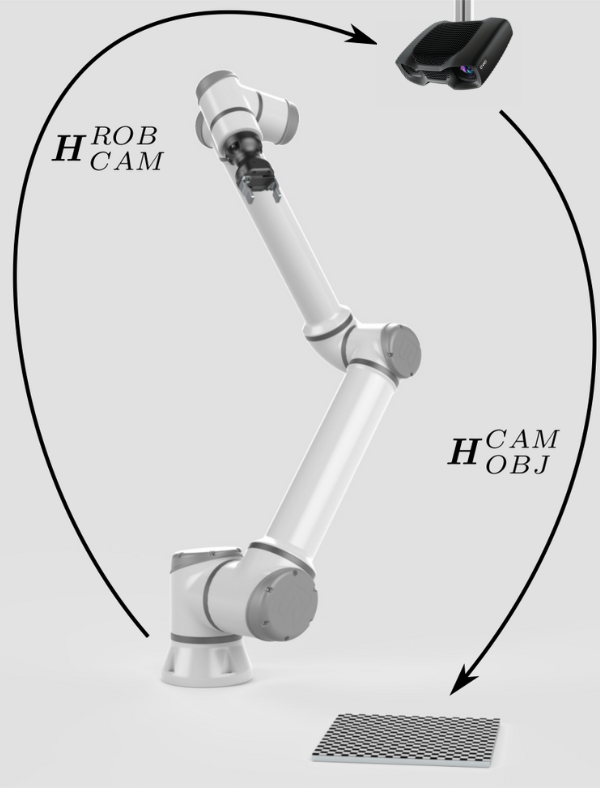
To calculate the relative pose between the camera and the robot (\(H^{ROB}_{CAM}\)), we somehow need to close the circle between the poses. |
|
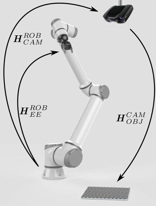
The pose of the end-effector relative to the robot base (\(H^{ROB}_{EE}\)) is also known, provided by the robot controller. |
|
The missing pose that will close the pose circle is the pose of the object relative to the end-effector (\(H^{EE}_{OBJ}\)). |
|
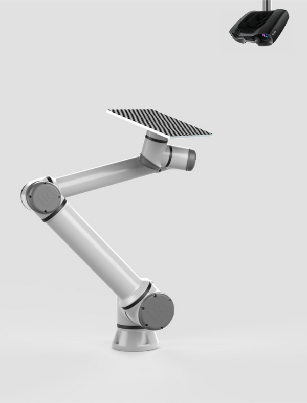
To get rid of this pose or fix it, we can mount the calibration object onto the end-effector. |
|
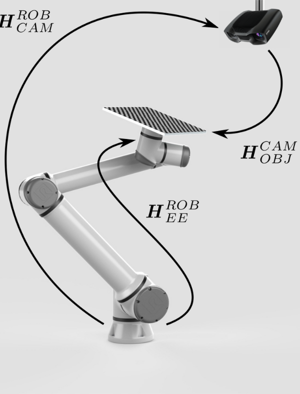
Now it seems we have everything to close the pose circle and thus calculate the pose of the camera relative to the robot (\(H^{ROB}_{CAM}\)). However, it is not that simple. |
|
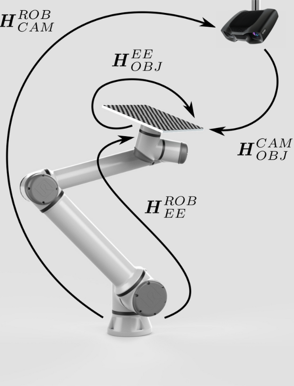
This is because we haven’t really got rid of the relative pose (\(H^{EE}_{OBJ}\)). However, we have made it constant, ensuring that pose of the calibration object relative to the end-effector (\(H^{EE}_{OBJ}\)) will not change during the motion of the robot. This enables us to move a robot to a set of different postures. For each one, \(H^{ROB}_{CAM}\) can be expressed as a function of the remaining two variable, known poses:
and one constant, unknown pose:
With this set of equations, it is possible to utilize an optimization technique, such as Tsai’s method, to calculate the desired pose \(H^{ROB}_{CAM}\). |
|
The first step is choosing a calibration object, e.g. a checkerboard. Zivid calibration objects (checkerboards and ArUco markers) will be covered in the next part of this tutorial. |
|
The calibration object is of known geometry. Thus, it can be detected from the camera image. Further, its pose relative to the camera (\(H^{CAM}_{OBJ}\)) can be estimated. |

|
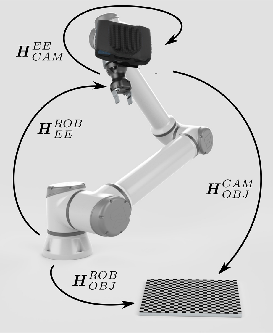
To calculate the relative pose between the camera and the end-effector (\(H^{EE}_{CAM}\)), we somehow need to close the circle between the poses. |

|
The pose of the end-effector relative to the robot base (\(H^{ROB}_{EE}\)) is also known, provided by the robot controller. |

|
The missing pose that will close the pose circle is the pose of the object relative to robot base (\(H^{ROB}_{OBJ}\)). |

|
To get rid of this pose or fix it, we must rigidly mount the calibration object. This is to ensure the pose of the calibration object relative to the robot base (\(H^{ROB}_{OBJ}\)) remains constant during the motion of the robot. |

|
Now we have everything to close the pose circle and thus calculate the pose of the camera relative to the end-effector (\(H^{EE}_{CAM}\)). During the hand-eye calibration process, the robot is moved to a set of different postures. For each one, \(H^{EE}_{CAM}\) can be expressed as a function of the remaining two variable, known poses:
and one constant, unknown pose:
With this set of equations, it is possible to utilize an optimization technique, such as Tsai’s method, to calculate the desired pose \(H^{EE}_{CAM}\). |
|
Now that we’ve explained how to solve the hand-eye calibration problem, let’s see learn about Hand-Eye Calibration Object options.