How To Use The Result Of Hand-Eye Calibration
We have analyzed the requirements for a robot that is accompanied by a Zivid camera and a machine vision software to pick an object. This led to the description of the Hand-Eye Calibration Problem. If you are unsure how to utilize the result of the hand-eye calibration, you are on the right page. This is where we describe how to transform the object’s coordinates from the Zivid camera coordinate system to the robot base coordinate system.
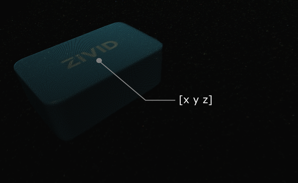
Let’s suppose you run machine vision software on a Zivid point cloud. It detects the object of interest, such as this Zivid gem, and estimates its position. The x, y, z values describing the picking point are given relative to the Zivid camera’s coordinate system.
Tip
Before running your application it is recommended to Warm-up the camera using the same capture cycle as for hand-eye calibration. To further reduce the impact of temperature dependent performance factors, enable Thermal Stabilization.
In some cases, your algorithm will also output the object’s orientation, e.g. the roll, pitch, and yaw angles. These parameters are also given relative to the Zivid camera’s coordinate system.
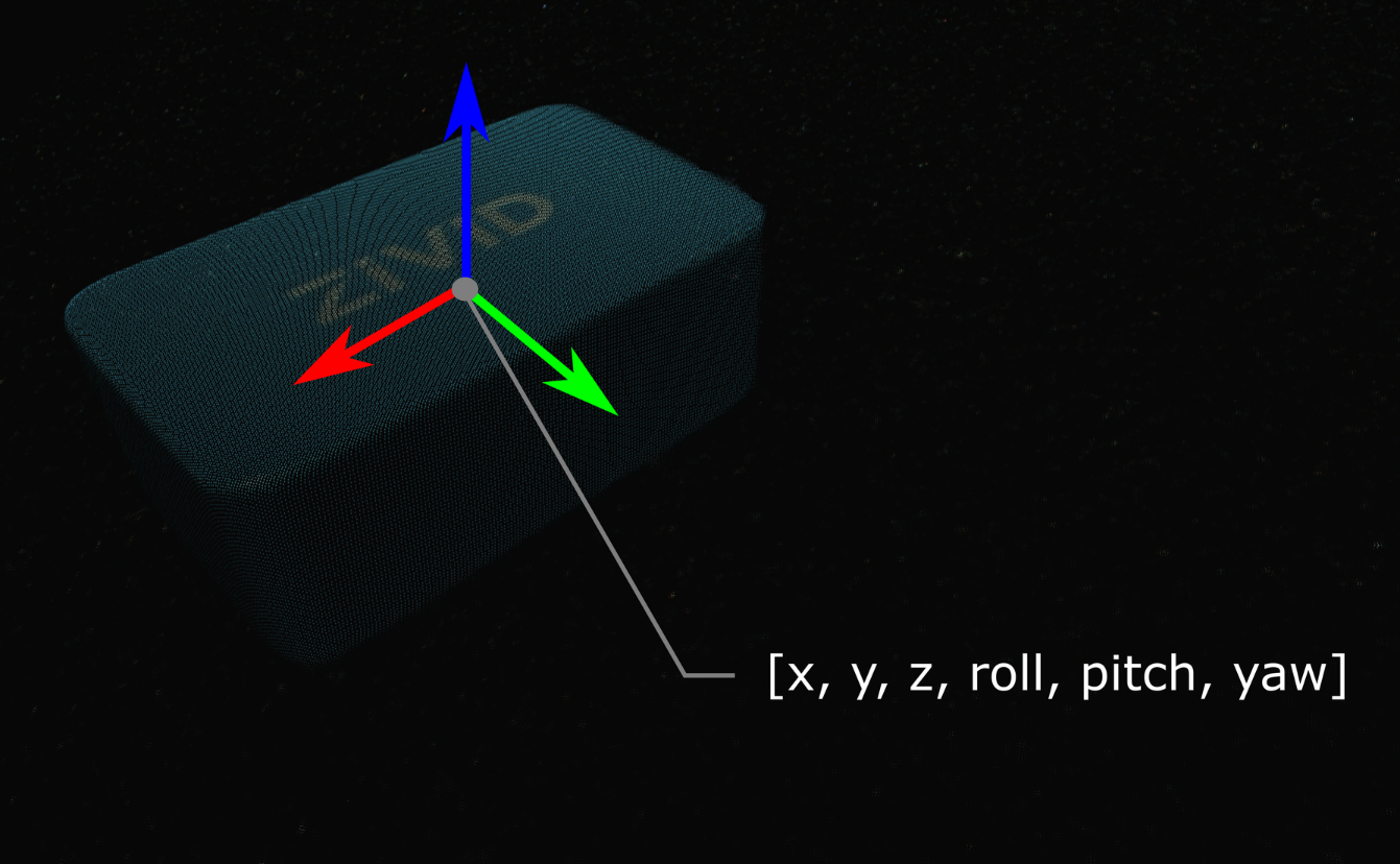
The pose (position and orientation) of your object can be described with a homogeneous transformation matrix. If you are not familiar with (robot) poses and coordinate systems, check out Position, Orientation and Coordinate Transformations.
In practice, the easiest way is to transform the point cloud from the camera to the robot base reference frame. The Zivid SDK supports transforming the data before it is copied to the CPU and is therefore very fast.
Below you will see the mathematical theory of transforming a single point or an entire point cloud from the camera to the robot base reference frame. This is followed by a code tutorial that demonstrates putting this into practice.
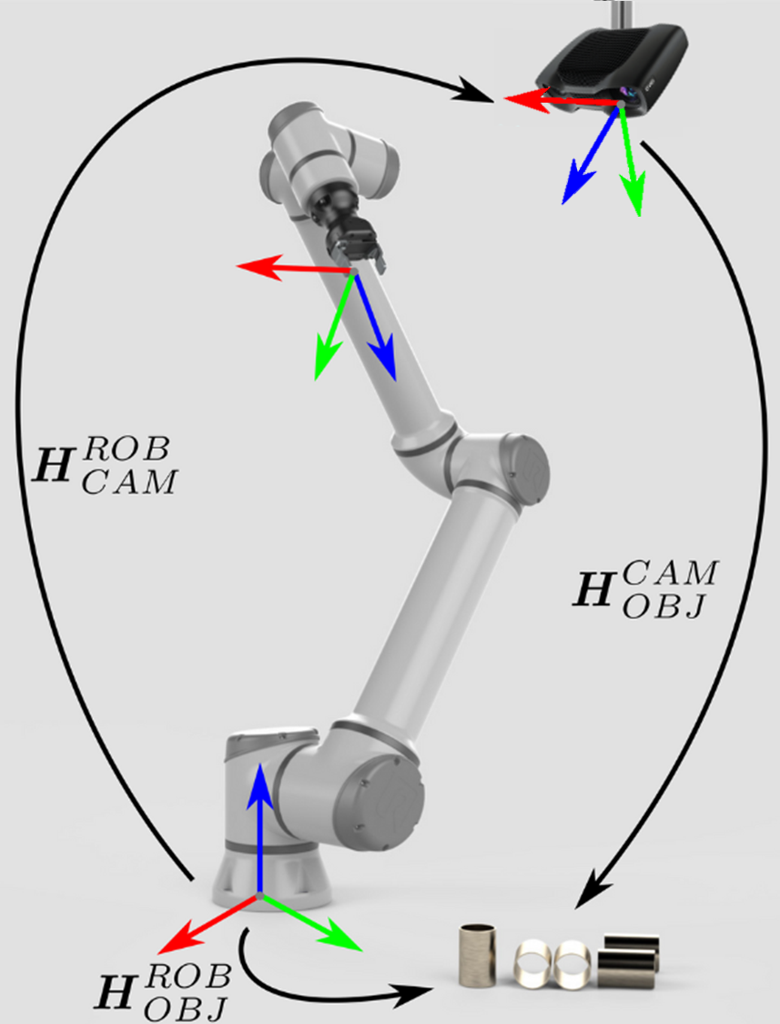
If you are dealing with an eye-to-hand system, this is how a single 3D point can be transformed from the Zivid camera to the robot base coordinate system:
To convert the whole Zivid point cloud, from the camera coordinate system to the robot base coordinate system, apply the equation above to each point in the point cloud.
On the other hand, to transform the pose of the object relative to the Zivid camera, apply the following equation:
We assume that your pose is described with a homogeneous transformation matrix. If it is not, you may want to check out our article on Conversions Between Common Orientation Representations.
The resulting pose is the one that the robot Tool Center Point (TCP) should attain for picking. The offset between the TCP and the robot’s flange should be accounted for on the robot side.
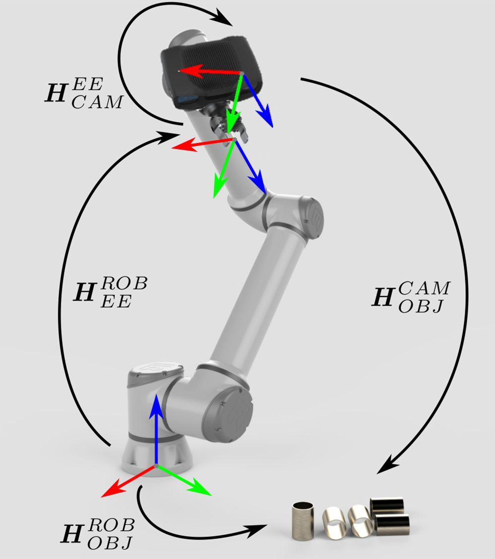
The approach for eye-in-hand systems is similar. The difference is that the current pose of the robot has to be included in the equations. As with the other poses, we assume that the robot pose is represented with a homogeneous transformation matrix. If your robot pose is represented differently, you may want to check out our article on Conversions Between Common Orientation Representations.
The following equation describes how to transform a single 3D point from the Zivid camera to the robot base coordinate system:
To convert the whole Zivid point cloud from the camera coordinate system to the robot base coordinate system, apply the equation above to each point in the point cloud.
To transform the pose of the object relative to the Zivid camera use the following equation:
The resulting pose is the one that the robot Tool Center Point (TCP) should attain for picking. The offset between the TCP and the robot’s flange should be accounted for on the robot side.
To put this theory into practice, let’s follow the tutorial to transform a single point or an entire point cloud from the camera to the robot base reference frame.

"""
Transform single data point or entire point cloud from camera to robot base reference frame using Hand-Eye calibration
matrix.

This example shows how to utilize the result of Hand-Eye calibration to transform either (picking) point coordinates
or the entire point cloud from the camera to the robot base reference frame.

For both Eye-To-Hand and Eye-In-Hand, there is a Zivid gem placed approx. 500 mm away from the robot base (see below).
The (picking) point is the Zivid gem centroid, defined as image coordinates in the camera reference frame and hard-coded
in this code example. Open the ZDF files in Zivid Studio to inspect the gem's 2D and corresponding 3D coordinates.

Eye-To-Hand
- ZDF file: ZividGemEyeToHand.zdf
- 2D image coordinates: (1035,255)
- Corresponding 3D coordinates: (37.77 -145.92 1227.1)
- Corresponding 3D coordinates (robot base reference frame): (-12.4  514.37 -21.79)

Eye-In-Hand:
- ZDF file: ZividGemEyeInHand.zdf
- 2D image coordinates: (1460,755)
- Corresponding 3D coordinates (camera reference frame): (83.95  28.84 305.7)
- Corresponding 3D coordinates (robot base reference frame): (531.03  -5.44 164.6)

For verification, check that the Zivid gem centroid 3D coordinates are the same as above after the transformation.

The YAML files for this sample can be found under the main instructions for Zivid samples.

"""
First, we get the camera pose in the robot base reference frame (result of eye-to-hand calibration).
The point cloud is given in the camera reference frame.

At this point, your machine vision software should detect the workpiece and estimate the picking point. In the example, we assume that the picking point is known, defined as image coordinates in the camera reference frame.
The picking point in the robot base reference frame is then calculated as follows. We first get the point cloud.
First, we get the following poses:
Camera pose in flange (end-effector) reference frame (result of eye-in-hand calibration)
Flange (end-effector) pose in robot base reference frame (current robot pose)
eye_in_hand_transform_file_path = get_sample_data_path() / "EyeInHandTransform.yaml"
robot_transform_file_path = get_sample_data_path() / "RobotTransform.yaml"

print("Reading camera pose in flange (end-effector) reference frame (result of eye-in-hand calibration)")
flange_to_camera_transform = load_and_assert_affine_matrix(eye_in_hand_transform_file_path)

print("Reading flange (end-effector) pose in robot base reference frame")
base_to_flange_transform = load_and_assert_affine_matrix(robot_transform_file_path)
By multiplying these two transformation matrices, we get the camera pose in the robot base reference frame.
The point cloud is given in the camera reference frame.

At this point, your machine vision software should detect the workpiece and estimate the picking point. In the example, we assume that the picking point is known, defined as image coordinates in the camera reference frame.
The picking point in the robot base reference frame is then calculated as follows. We first get the point cloud.
Then, from the point cloud, we get the picking point (XYZ coordinates) in the camera reference frame.
print("Transforming single point")

xyz = point_cloud.copy_data("xyz")

point_in_camera_frame = np.array(
    [
        xyz[image_coordinate_y, image_coordinate_x, 0],
        xyz[image_coordinate_y, image_coordinate_x, 1],
        xyz[image_coordinate_y, image_coordinate_x, 2],
        1,
    ]
)
print(f"Point coordinates in camera reference frame: {point_in_camera_frame[0:3]}")
Finally, we transform the picking point to the robot base reference frame.
Instead of transforming only the picking point, we can transform the whole point cloud to the robot base reference frame. This enables your machine vision software to find the picking point in the robot base reference frame directly from the point cloud.

To get the point cloud in ZDF format, you can run the code sample or download it as part of Sample Data (ZividGemEyeToHandInRobotBaseFrame.zdf).

To get the point cloud in ZDF format, you can run the code sample or download it as part of Sample Data (ZividGemEyeInHandInRobotBaseFrame.zdf).
Version History
SDK |
Changes |
|---|---|
2.12.0 |
Add a section on how to utilize the result of hand-eye calibration to transform the object’s coordinates from the Zivid camera coordinate system to the robot base coordinate system. |