Contrast Distortion
A phenomenon called contrast distortion occurs due to imperfections in the lens and optical phenomena like diffraction and chromatic aberrations. The optical imperfections cause a slight blur between neighboring pixels, and it happens even at “perfect” focus distance. Depending on the size of the camera aperture and the corresponding depth of field and distance from the correct focus distance, the pixel blurring increases.
Note
Contrast distortion is caused by blurring in the camera lens.
Contrast distortion appears when we have an abrupt change from a highly absorptive to a reflective surface. This could be the black to white transition on a checkerboard or regions with specular reflections, like a shiny metal cylinder. The errors are visible as surface distortion/deformation artifacts in the 3D point cloud. This artifact is also called the Laplacian effect because the distortion curve in the point cloud looks like a laplacian curve.
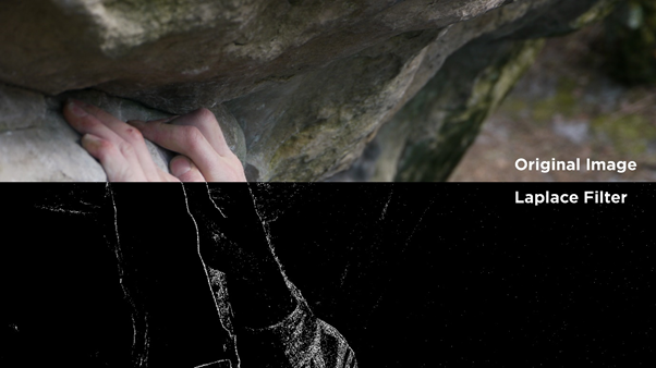
The image below depicts a 2D image where a Laplacian filter is applied on the bottom half to demonstrate the intensity transition. Notice how the filter highlights the edges, i.e. transitions in the color image wherever the intensity changes.
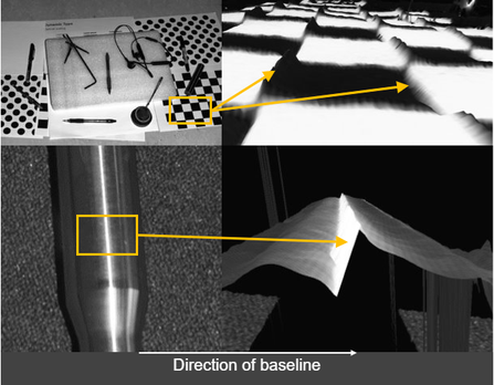
Contrast distortion occurs along the image x-axis (camera’s baseline) but not along the y-axis. The strength of the contrast distortion depends on the gradient of the change in intensity within a small region of pixels. A sharp or significant gradient produces a more pronounced distortion in the point cloud, as seen in the image below.
Warning
Contrast distortion only occurs along the camera’s baseline.
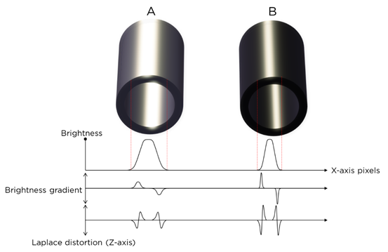
Let’s look at two similar cylinders, A and B. Cylinder B has a greater difference in brightness between dark and bright areas along its body compared to cylinder A. Additionally, the intensity transition area of cylinder B is narrower, and therefore, the brightness gradient steeper. These two characteristics enhance the undesirable effect the contrast distortion has on the point cloud of cylinder B; the artifact gets taller and steeper.
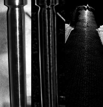
An example of a strong contrast distortion is demonstrated in the image below. On the left side, we can see a very polished metal cylinder which is aligned parallel to the y-axis of the 2D camera and the projector. A white stripe down the middle of the cylinder is the light from the projector being reflected directly to the camera. Down either side of the white stripe the light is reflected away from the camera, causing the object to appear darker on the sides.
Together, the different directions of reflection create a strong contrast distortion effect which can be seen as a black stripe in the second image. In the resulting point cloud to the right, the over-exposure along the surface of the cylinder creates a “ridge” which distorts and deforms the cylinder from its true, cylindrical shape.
To correct and/or remove this artifact, check out how to Deal with the contrast distortion.