Depalletization - Imaging at Large Distance
Introduction
In this article, we will learn how to apply appropriate imaging techniques using the Zivid One+ Large camera in a stationary mounting condition for large distances and working range. A typical scenario where this will be useful is in what is known as depalletization applications, where vision-guided robots will unload objects that are stacked on pallets. The objects may be either of same or mixed stock-keeping unit, and very often box-shaped. In this article, we will assume that the objects are mixed, both in size and color, and little to moderately glossy/shiny. Next, we will look closer at the assumed specifications.
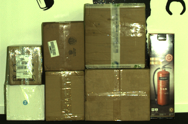
For illustrating most of the procedures and techniques described in this article, we will refer to the scene that can be seen in the image below.
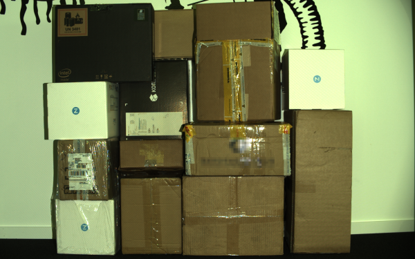
The objects in this scene cover an area of approximately \(1200 \times 1200 \text{ mm}^2\). They consist of a mix of boxes including black and white with a glossy finish, regular cardboard boxes, boxes wrapped in plastic foil, boxes with logos and boxes with tape. In our examples, the camera is positioned so that it is aligned approximately with the center of the objects. However, we always recommend that you tilt the Zivid camera at an angle. This helps to avoid direct reflections and related artifacts, and also to reduce the dynamic range required for the acquisition. See our general recommendations for camera positioning.
Specification
Parameter |
Spec / requirement |
|---|---|
Pallet area (Field-of-View) |
\(\leq 1200 \times 1200 \text{ mm}^2\) |
Pallet height (Working distance / working range) |
\(\leq 2000 \text{ mm}\) |
Object volume |
\(\geq 50 \times 50 \times 50 \text{ mm}^3\) |
Object color |
Any (including white and black) |
Object specularity |
Little to moderately shiny/glossy (not metal or glass) |
Imaging time budget |
\(\leq 2.5 \text{ s}\) |
Camera mounting
We will assume that the Zivid camera will cover the entire working volume from a fixed position. To be able to image a square area of \(1200 \times 1200 \text{ mm}^2\), the Zivid One+ Large camera needs to be mounted 2.75 m above the top layer. You can calculate the necessary height for your application using our online distance (or FOV) calculator which can be found here: Calculate FOV and Imaging Distance. The maximum stacking height is set to 2 meters. Thus, in this example, the Zivid camera needs to be mounted at a height of 4.75 m (total height of objects stacked on the pallet). This means that the distance to the bottom layer is about 4.5 m which is outside of the recommended working range of the Zivid One+ Large camera. Therefore, extra care needs to be taken to ensure that the output point clouds are of sufficient quality.
Impact of working at large distances
Spatial resolution and depth noise
It is important to be aware that the spatial resolution and noise level of the Zivid camera increases with distance. In our assumed example, the spatial resolution at the top of the pallet will be about 1 mm, while at the bottom it will be about 1.8 mm. This means that the resolution is almost half at the bottom layer, and in addition, the noise will be 5-8 times higher than at the top layer. One potential consequence of this are that the spatial resolution may set a limit to how tightly stacked objects can be separated using the Zivid’s 2.3 MP sensor only. It may also require pose estimation algorithms that exhibit higher levels of insensitivity against noise.
Depth-of-focus
The focus point of the Zivid One+ Large camera is at 2 m. Therefore, another potential challenge from capturing images at far distances is that the image may become out of focus which will have some impact to the point cloud quality. By using sufficiently low aperture values we can ensure that the image achieves acceptable focus. In our example of imaging objects at a distance of up to about 4.5 m, it is recommended to use aperture (f-number) higher than 3.4. You can calculate the maximum recommended f-number values for your particular application by using our Depth of Focus Calculator. A suitable value for the “Acceptable Blur Radius (pixels)” is 1.5.
Ambient light
The last item that we will discuss is the increased sensitivity to ambient light at larger distances. Be aware that ambient lights in e.g. warehouse ceiling will emit light that will blend with the projected light from the Zivid camera. Since the structured light technology employed by the Zivid camera is dependent on being able to see the emitted light, this will directly impact the noise in the point cloud. You can read more about the effects of ambient light here: Dealing with Strong Ambient Light.
It is good practice to control and eliminate ambient light whenever possible. Always consider the possibility of turning off lights or in some cases even to cover the working area of the 3D sensor. It is a much-debated and sensitive topic, but we strongly advise to always consult the possibility of controlling ambient lighting with the client/customer.
Adjusting the camera settings for far distance imaging
In this section, we will:
present a set of camera settings that suits the specifications described in the introduction.
look at how the various camera settings can affect the point cloud.
look at how we went about to choose the settings we did.
establish some imaging principles and techniques.
Exposure settings
The table below shows the exposure settings for our application. They provide a good tradeoff between dynamic range and signal-to-noise ratio while meeting the timing requirements set by the application specifications when running on a high-performance computer. This in effect will increase the chances of receiving high-quality point clouds from the camera.
Acquisition # |
Exposure Time |
Aperture (f-number) |
Brightness |
Gain |
Comment |
|---|---|---|---|---|---|
1 |
40 000 |
5.66 |
1.8 |
1.0 |
Highlight acquisition aimed at covering white/bright objects such as transparent/reflective tape and wrapping |
2 |
40 000 |
4.0 |
1.8 |
2.0 |
Mid-tone acquisition aimed at covering the majority of the scene |
3 |
40 000 |
2.8 |
1.8 |
4.0 |
Lowlight acquisition aimed at covering especially dark objects when imaging at a far distance |
4 |
40 000 |
4.0 |
1.8 |
2.0 |
Duplicate of acquisition #2 to suppress noise and improve point cloud quality |
5 |
40 000 |
5.66 |
1.8 |
1.0 |
Duplicate of acquisition #1 to suppress noise and improve point cloud quality |
Below we will go through the techniques and principles we applied to arrive at these settings.
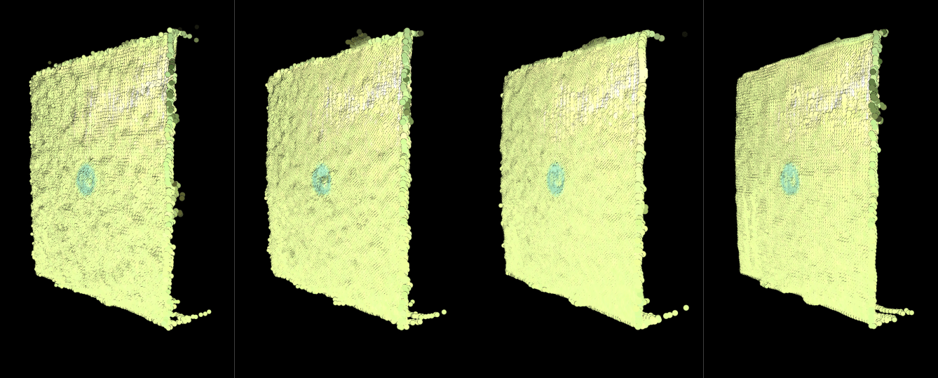
HDR - capturing point clouds using multiple acquisitions will take advantage of the inherent noise suppression effect in Zivid’s HDR algorithm. Therefore it is recommended to use as many acquisitions as possible within the given time budget to achieve optimal noise performance. In our application, we will benefit more from duplicating the same acquisition(s), typically the mid-tone and/or lowlight, rather than spanning out the dynamic range even more. For our application, an acceptable dynamic range will typically be achieved by using 2-3 acquisitions. If more capturing time is available beyond these 2-3 acquisitions, we will further improve point cloud quality by duplicating these acquisitions as many times as we can afford.
The image below shows the effect of applying this HDR technique. The leftmost point cloud is captured with a single acquisition. The second point cloud is captured with a 2-acquisition HDR. The third is captured with a 5-acquisition HDR. The rightmost point cloud is captured with an 8-acquisition HDR.
An example (point cloud to the right in the image above) of an HDR set that utilizes this noise suppression technique is illustrated in the table below:
Acquisition #
Exposure Time
Aperture (f-number)
Brightness
Gain
Stops
1
40 000
5.66
1.8
1.0
0 (normalized)
2 (duplicate of acquisition #1)
40 000
5.66
1.8
1.0
0 (normalized)
3 (duplicate of acquisition #1)
40 000
5.66
1.8
1.0
0 (normalized)
4
40 000
4.0
1.8
2.0
+2
5 (duplicate of acquisition #4)
40 000
4.0
1.8
2.0
+2
6 (duplicate of acquisition #4)
40 000
4.0
1.8
2.0
+2
7 (duplicate of acquisition #4)
40 000
4.0
1.8
2.0
+2
8
40 000
2.8
1.8
4.0
+4
Exposure Time - If you observe ripple patterns on the box surfaces, there is interference with an AC powered artificial light source. This can be confirmed by turning off nearby light sources. Use multiples of 10000 us for exposure time if your grid frequency is 50 Hz and multiples of 8333 us if it is 60 Hz.
Projector Brightness - Increase signal intensity by boosting the projector brightness setting to its maximum (1.8); this increases the SNR, thus reducing the negative effect of ambient light.
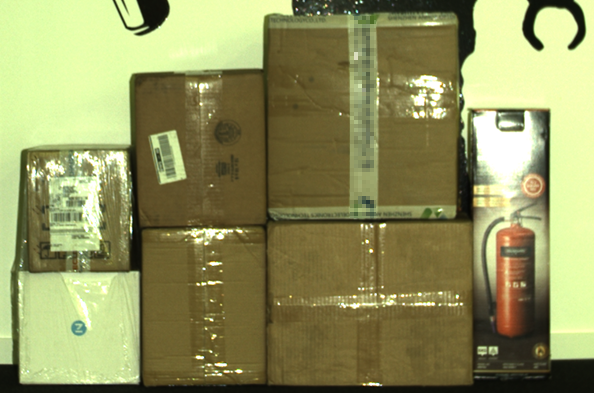
Aperture - As the f-number value decreases, the depth of focus narrows. This means you need to find the lower limit for the f-number value that keeps the boxes in the depth of focus, see the Depth of Focus Calculator. For example, for the f-number 4.27, if the acceptable blur radius is 1 pixel, the depth-of-field spans from 1.4 to 4 m of working distance, which fully covers the boxes.
Below is a comparison of two images taken with different aperture settings. The first image is taken with a very low f-number and it is blurry. The second image is taken with the f-number that keeps the boxes in the depth of focus. Artifacts are much more pronounced when images are defocused and therefore noisier.
Filter settings
We will use the following filter settings for our application:
Filter |
Filter value |
Comment |
Noise |
7.0 |
These values keep relative point cloud density consistent across the entire working range. |
Outlier |
75 |
|
Gaussian |
2.5 |
This value averages noise when imaging at large distances. |
Reflection |
Enabled |
Not strictly necessary, but we use it in this application as a precaution against reflections. We recommend that you also try to disable it in your application to save capture time. |
Below we will go through the techniques and principles we applied to arrive at these settings.
-
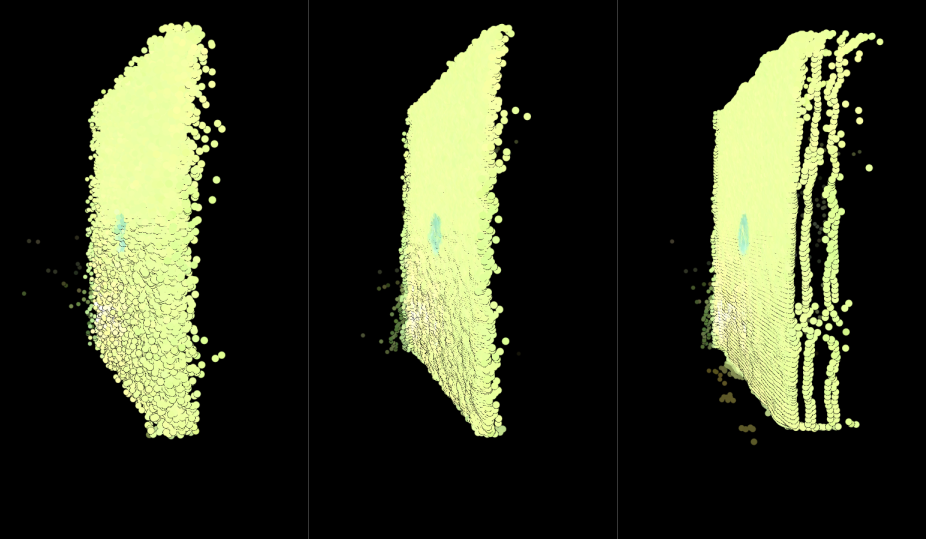
Use this filter to suppress the noise and align pixels to a grid. For this application, it is likely more important to get smooth surfaces on the boxes than to get accurate points in order to estimate the pick/grasp position of the object. The Gaussian filter should also help for calculating normals. Imaging at large distances most likely requires the Gaussian filter.
The image below shows the effect of applying the Gaussian filter with the strength (or sigma) increasing from left to right.
-
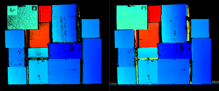
Since we are imaging at very large distances, we need to increase this threshold value in order to preserve as many points as possible. In our example, we will use an outlier threshold of 75 mm. The 75 mm outlier compared to 25 mm means you will have more noise on the boxes and elsewhere in the scene. However, this can be compensated by using e.g. the Noise and Gaussian filters.
The image below shows the depth maps of two point clouds taken of the same scene at about 4.5 m with two different outlier threshold values. The image to the left uses an outlier threshold of 25 mm and 75 mm to the right. As we can see, especially from the top left box, using outlier threshold of 25 mm results in a sparse point cloud.
-
Set the threshold low to get as many points as possible. This is necessary since the effect that ambient light has on the noise in the point cloud grows with the imaging distance. Using lower SNR values will make sure you get all the points that you can, especially on dark/black objects. The points that are regained by reducing the threshold will be noisier. This can be compensated for using the Gaussian filter and the inherent noise reduction effect from HDR described above. When imaging objects that have a diffuse and bright surface, such as white or cardboard boxes without transparent tape or wrapping, using a higher SNR value is ok (e.g. SNR=10). In our assumed application, we will use a SNR value of 7 to get more data on black objects.
The image below shows how reducing the noise threshold reveals more points. To the left a noise threshold of 14 was used, 10 in the middle, and 7 to the right. It can be seen that the rightmost point cloud is clearly denser, especially in the regions with black boxes.

Results
When we apply the camera settings we found, we are able to image all the mixed objects in the scene with good noise performance. Below we find two point clouds taken at the near and far distances with the proposed settings and configurations.
Point cloud as imaged from 2.75 m distance
Point cloud as imaged from 4.5 m distance
Contributions from each acquisition exposure setting
The image below shows the 3 individual acquisition settings and how they contribute to the scene illustrated in the 2D image.
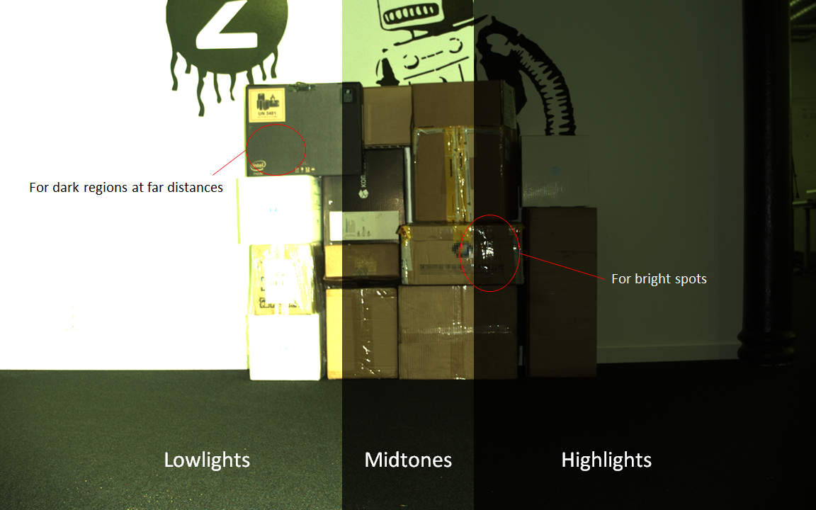
As we can see, the lowlight acquisition (which has the highest exposure values) clearly illuminates dark regions. At the same time there are many regions that become oversaturated, and thus need to be captured by the mid-tone acquisition instead. The mid-tone acquisition is the most important acquisition as it reveals the majority of the point cloud that we are interested in. The highlights acquisition helps to get data in regions with a lot of reflections such as from the tape.
Other considerations
Cropping the point cloud
In order to not waste compute power on processing points that are outside the working region we recommend that you crop your point cloud. Cropping can be based roughly on the position of the pallet relative to the Zivid camera in addition to cropping points that are too close or too far. E.g. dynamically change your depth tolerance for each layer on the pallet.
Robot mounting
By operating the Zivid camera within the recommended working range the Zivid cameras will inherently exhibit higher performance and ambient light resilience. The result is point clouds with both higher density and quality in shorter capture times. In this article we used about 2.5 seconds to acquire a point cloud, while in a robot mounted configuration a comparable capture would typically take from 0.3 to 1 seconds. This will make the achievable duty cycle in depalletization applications very comparable between stationary and robot mounting applications. Another benefit of robot mounting is the increased flexibility and ground area coverage as the same camera can serve multiple stations.
Summary
In this article we have learned one method for capturing high density point clouds with low noise when operating the Zivid camera outside of its recommended working range. By applying averaging and filtering techniques we were able to reveal a wide variety of objects in the same scene. The point cloud has low degrees of noise and other artifacts even at distances up to 4.5 m.