Robot Mounting
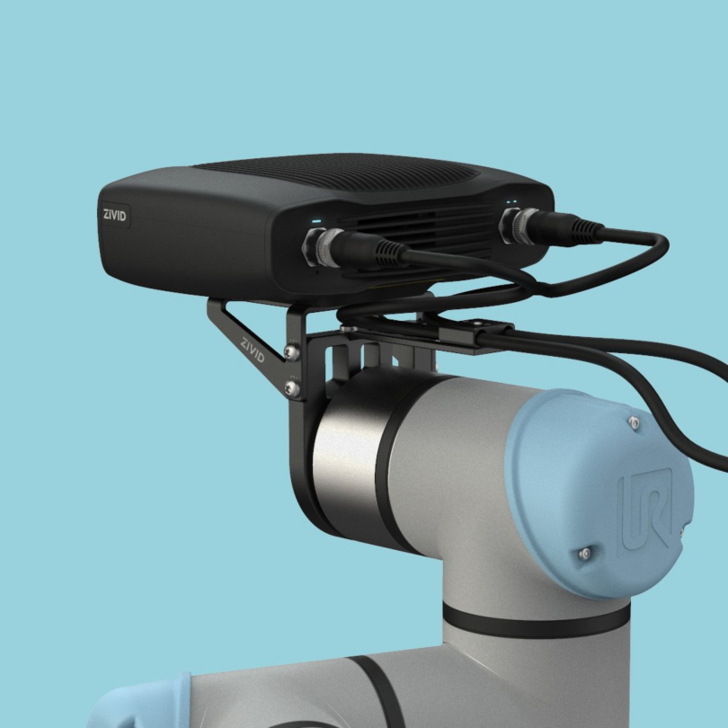
All Zivid 3D camera models can be mounted on a robot. However, Zivid 2 and Zivid 2+ models are especially suited for on-arm mounting because of their compact size, light weight, capture speed, and specialized field of view.
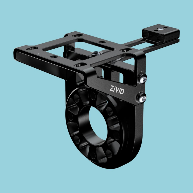
Zivid On-Arm Mount
Zivid On-Arm Mount is a mount for attaching a Zivid camera to industrial and collaborative robots.
Why use Zivid On-Arm Mounting solution?
Lightweight
Zivid On-Arm mount is lightweight, designed to have a low impact on the carrying capacity of the robot arm, which is especially important for collaborative robots and more miniature industrial robots. This allows for heavier tools and grippers to be used as well as getting the most payload possible from the system.
Modularity
One camera bracket fits all our camera models, and replacing the camera is possible without complete disassembly.
Integrated cable management
Zivid On-Arm Mount has a strain relief on the camera end, which protects the connectors in case of cable entanglement. It can be installed at the back of the camera or to either side, allowing for adaptability to each unique mounting scenario.
Occlusion prevention
Two camera bracket options give the choice of flat or 15-degree tilted mounting, suitable for large grippers that occlude the camera view.
Flexibility and collision prevention
Since it has a low profile, Zivid On-Arm Mount reduces the risk of collision with other objects and provides good clearance of the gripper and robot arm. Extender(s) and flexible configuration allow for multiple mounting poses, e.g., the camera bracket can be oriented in two ways. Such setups enable the camera to stay clear of large grippers and gain headroom for challenging robot movement, thus preventing self-collision. Mounting the tilted camera bracket in a backward orientation makes the camera look more toward the gripper, potentially reducing the required robot motion.
Adaptability
Since it comes in multiple variants, Zivid On-Arm Mount supports various robots. In addition, its modular design allows for easy customization of the adapter to fit more robots.
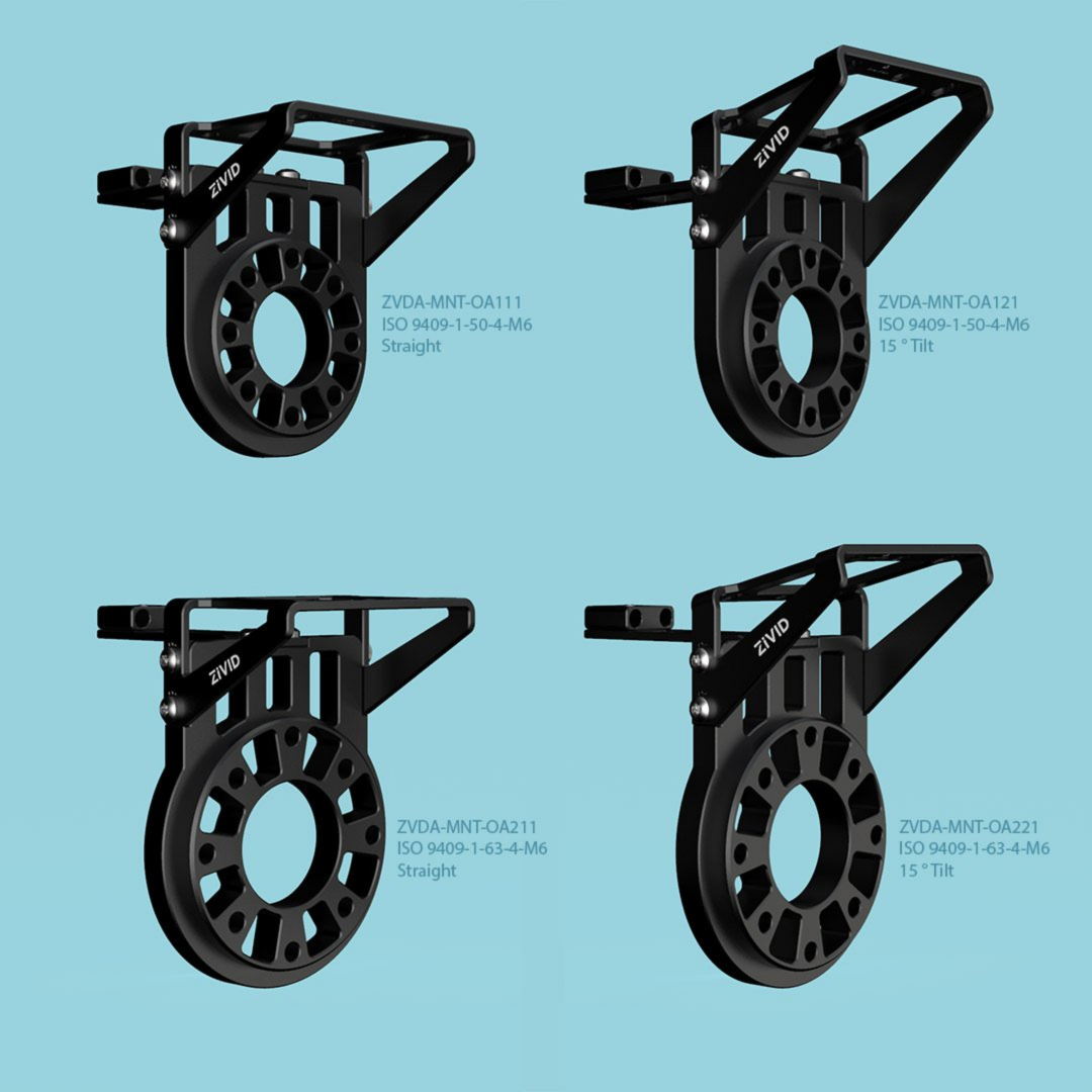
Zivid On-Arm Mount Variants
There are four variants of the Zivid On-Arm Mount:
- ZVDA-MNT-OA111
Straight camera bracket
Flange adapter compatible with ISO 9409-1-50-4-M6 (UR, Omron, Doosan, ++)
- ZVDA-MNT-OA121
15-degree tilt on camera bracket (recommended when using grippers that can create occlusion)
Flange adapter compatible with ISO 9409-1-50-4-M6 (UR, Omron, Doosan, ++).
- ZVDA-MNT-OA211
Straight camera bracket
Flange adapter compatible with ISO 9409-1-63-4-M6 (Yaskawa, Kawasaki, ++)
- ZVDA-MNT-OA221
15-degree tilt on camera bracket (recommended when using grippers that can create occlusion)
Flange adapter compatible with ISO 9409-1-63-4-M6 (Yaskawa, Kawasaki, ++)
The datasheet and user guide in PDF and CAD files can be found at Accessories Downloads.
Zivid On-Arm Mount Extender
Zivid On-Arm Mount Extender is a separate (optional) product that adds mounting flexibility.
Zivid On-Arm Mount Extender Variants
There are two variants of the extender:
- ZVDA-MNT-OA01E
Compatible with ISO9409-1-50-4-M6 flanges (UR, Omron, Doosan, ++)
- ZVDA-MNT-OA02E
Compatible with ISO9409-1-63-4-M6 flanges (Yaskawa, Kawasaki, ++)
The datasheet can be found at Accessories Downloads.
Mounting Instructions
In the box, you will find a camera bracket, strain relief for cable management, a robot flange adapter, and mounting screws.
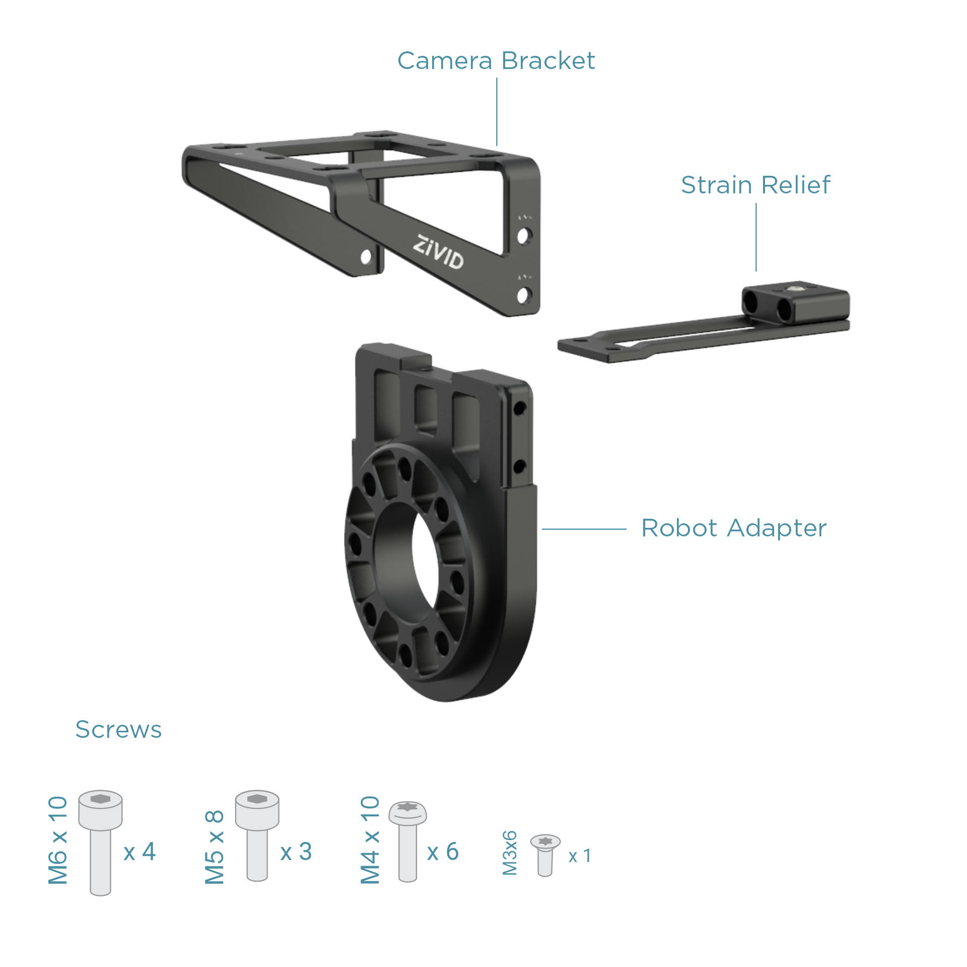
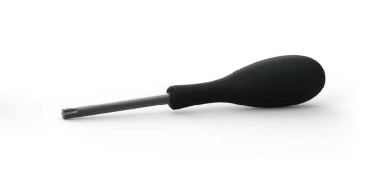
The following tools are required for installation:
Torx 20, 25, and 30
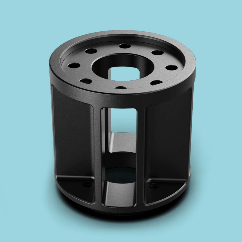
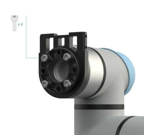
Robot Adapter and Extender
The optional extender can be installed behind or in front of the robot adapter. Install it in front to keep the camera at a longer distance from the gripper, thus minimizing the risk of collision during picking with, e.g., bin edges. Installing the extender behind the robot adapter is suitable for reducing the risk of robot self-collision for some robots, and it also gives good cable management options.
Regardless of which mount component you are fixing to the robot flange, check appropriate robot documentation for recommended screw type and torque values before installing it with four screws. We recommend using screws in stainless steel (A2 or A4). The extender comes with stainless steel mounting screws. However, the on-arm mount is not supplied with mounting screws.
Check the robot documentation to see how deep the screws should enter the robot flange. The robot adapter adds 12.5 mm of length needed for the screws. A screw depth of approximately 5 mm is usually suitable.
For added flexibility, more extenders can be added. However, be mindful of the robot’s carrying capacity and don’t underestimate the inertia forces generated by off-center payloads.
Locating Dowel Pin
We recommend using a dowel pin with h-tolerance to fix the on-arm mount with the robot flange.
Warning
Do not use m-tolerance positioning pins; they will get stuck.
If installing the extender behind the robot adapter, use a Ø6 mm dowel pin for connecting the extender with the robot flange. The dowel pin should enter the extender 6 mm deep. Check the robot documentation to see how deep the dowel pin should enter the robot flange; a 10 mm long dowel pin is usually suitable.
If installing the extender in front of the robot adapter, the locating dowel pin must be 20-22 cm long because it needs to pass through it.
If not using the extender, the dowel pin should enter the robot adapter 5 mm deep.
Tip
The locking dowel pin ensures good repeatability when reassembling the mount and no movement of adjoined components over time, even if exposed to considerable physical harm.
Strain Relief
Install the strain relief as shown in the image below.
Note
The strain relief can also be installed forward facing with the cable clamp pointing towards the gripper.
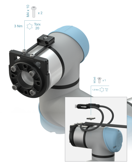
Tip
The strain relief protects the camera connectors if the cables get entangled by minimizing the risk of force being exerted directly on the cable connectors, physically damaging them. The strain relief component will help channel the unwanted force coming from entangled cables into the robot arm, giving it a chance to stop movement. In addition to the strain relief, use an adequate cable management system, e.g., Igus Cable Management Solutions.
Camera Bracket
Mount the camera bracket.
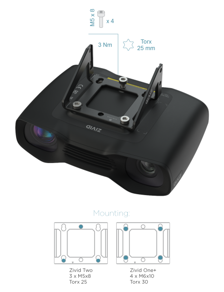
Note
Since the camera mounting bracket is symmetrical, it is possible to mount it backward (with the arrow on the camera bracket pointing backward). This leaves more space between the gripper and the camera.
Mount the camera by sliding the camera bracket onto the rails of the robot adapter.
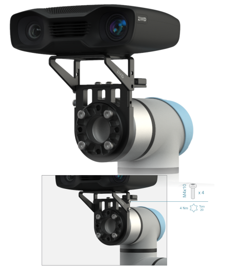
Tip
For additional safety to prevent screws from getting loose, we recommend using Loctite (purple or blue) and Nordlock washers. Regular flat washers will not help with vibrations but will help ensure the correct depth for screws entering a particular component.
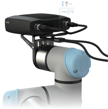
Cables
Attach cables and guide them through the strain relief. The cable clamp is designed for 5-7 mm diameter cables.
Note
The strain relief on the Zivid On-Arm Mount is designed for use with Zivid power and data cables. Using thicker third-party or custom cables is also possible with our mount, but then instead of using the cable clamp, fix the cables to our strain relief with cable ties.
Warning
Keep in mind that we do not recommend using any cables other than the ones supplied by Zivid.
The cable between the camera and the strain relief should be relatively loose to avoid constant static bending and twisting forces on the connectors, damaging them over time. When using the Zivid On-Arm Mount, we recommend leaving 20-30 cm of the cable length between the camera and the strain relief component. The cables going out of the camera should form a small loop before entering the strain relief component.
An alternative option is to route the cables via the side opening of the Zivid Mount Extender. In that case, use 30-40 cm of the cable length between the camera and the strain relief component.
Tip
Power and Ethernet cables with angled 90-degree connectors fit well with the Zivid On-Arm Mount. Since the cables are directed downwards and take up little space, using 90-degree connectors is safer than with straight connectors as it reduces the risk of entanglement.
Note
It is possible to use the strain relief on the Zivid On-Arm Mount with straight or angled camera brackets installed forward or backward. However, with the camera brackets installed backward, you will lose access to the screws on the cable clamp. Alternatively, you can install the strain relief component on the side of the Zivid On-Arm mount.
We recommend some form of strain relief also on the PC side to prevent the connectors or ports from getting damaged.
For additional collision protection, check out the Protective Housing.
Read Mechanical Considerations for Robot Mounting to be sure you are making the right decisions regarding purchasing or designing, integrating, and installing accessories and equipment for robot mounting.
Continue reading about Tripod Mounting.