Transform
Tip
Our webinar Getting your point cloud ready for your application partly covers Transform.
Introduction
This article explains a transformation in a point cloud context, how to transform a Zivid point cloud, and why this is a valuable feature. Lastly, it provides a tutorial with code examples.
Zivid point clouds are given relative to the Zivid camera coordinate system. Different applications for various reasons require transforming the whole point cloud or its segment, e.g., ROI or pick point, from the camera coordinate system to another coordinate system.
Problem |
The Point cloud is given in the camera coordinate system, but the application requires the point cloud given in another coordinate system. |
Solution |
Transform the Zivid point cloud to another coordinate system. |
Transform in API
A rigid transformation is defined by a 4×4 homogeneous transformation matrix that describes the pose of one coordinate system relative to another. Once the transformation matrix is known, we can use Zivid SDK to transform the point cloud from the camera coordinate system to the desired coordinate system.
Tip
Zivid SDK allows all affine transformations, including non-rigid ones. An example of a non-rigid transformation is scaling the point cloud by converting it from mm to m.
As an example, say you have detected the Zivid calibration board and estimated its pose.

std::cout << "Detecting and estimating pose of the Zivid checkerboard in the camera frame" << std::endl;
const auto detectionResult = Zivid::Calibration::detectCalibrationBoard(frame);
const auto cameraToCheckerboardTransform = detectionResult.pose().toMatrix();
std::cout << "Camera pose in checkerboard frame:" << std::endl;
const auto checkerboardToCameraTransform = cameraToCheckerboardTransform.inverse();
Console.WriteLine("Detecting and estimating pose of the Zivid checkerboard in the camera frame");
var detectionResult = Detector.DetectCalibrationBoard(frame);
var cameraToCheckerboardTransform = new Zivid.NET.Matrix4x4(detectionResult.Pose().ToMatrix());
Console.WriteLine("Camera pose in checkerboard frame:");
var checkerboardToCameraTransform = cameraToCheckerboardTransform.Inverse();
print("Detecting and estimating pose of the Zivid checkerboard in the camera frame")
detection_result = zivid.calibration.detect_calibration_board(frame)

if not detection_result.valid():
    raise RuntimeError(f"No Checkerboard detected. {detection_result.status_description()}")

camera_to_checkerboard_transform = detection_result.pose().to_matrix()
print("Camera pose in checkerboard frame:")
checkerboard_to_camera_transform = np.linalg.inv(camera_to_checkerboard_transform)
This transformation matrix can then be used to transform the point cloud to the checkerboard coordinate system.
std::cout << "Transforming point cloud from camera frame to checkerboard frame" << std::endl;
pointCloud.transform(checkerboardToCameraTransform);
Console.WriteLine("Transforming point cloud from camera frame to checkerboard frame");
pointCloud.Transform(checkerboardToCameraTransform);
You can save the transformation matrix to file, and also load it from file.
const auto transformFile = "CheckerboardToCameraTransform.yaml";
std::cout << "Saving camera pose in checkerboard frame to file: " << transformFile << std::endl;
checkerboardToCameraTransform.save(transformFile);
var transformFile = "CheckerboardToCameraTransform.yaml";
Console.WriteLine("Saving camera pose in checkerboard frame to file: " + transformFile);
checkerboardToCameraTransform.Save(transformFile);
The point cloud is transformed in-place, meaning you can save the transformed point cloud to file from the frame.
const auto checkerboardTransformedFile = "CalibrationBoardInCheckerboardOrigin.zdf";
std::cout << "Saving transformed point cloud to file: " << checkerboardTransformedFile << std::endl;
frame.save(checkerboardTransformedFile);
var checkerboardTransformedFile = "CalibrationBoardInCheckerboardOrigin.zdf";
Console.WriteLine("Saving transformed point cloud to file: " + checkerboardTransformedFile);
frame.Save(checkerboardTransformedFile);
Similarly, you can also load a transformed point cloud. To recover the original point cloud, you can read out the applied transformation matrix to transform it back again.
std::cout << "Reading applied transformation matrix to the point cloud:" << std::endl;
const auto transformationMatrix = pointCloud.transformationMatrix();
std::cout << transformationMatrix << std::endl;
Console.WriteLine("Reading applied transformation matrix to the point cloud:");
var transformationMatrix = pointCloud.TransformationMatrix;
Console.WriteLine(transformationMatrix);
Note
Transform API in Zivid SDK is fast because it is done on the GPU, in parallel, while the point cloud data is still on the GPU memory. Transform implementations with third-party libraries are likely more time-consuming: CPU computations are much slower in general, and GPU computations require another copy. See Point Cloud Capture Process for more info.
Tip
For better performance, use the transform API together with the downsample and normals APIs. This ensures that all computations are performed by the GPU while the point cloud data remains in GPU memory.
For the fastest implementation, first, downsample the point cloud, then transform it.
Compute normals after transforming the point cloud to have the normals in the same coordinate system as point cloud.
To learn more about poses and transformations, check out Position, Orientation and Coordinate Transformations.
Transform in Zivid Studio
You can also apply transformations to the point clouds in Zivid Studio. After having captured, navigate to the Transform drop-down at the top of the current view. Among others, you can load a transformation matrix from file, set it to the coordinate system of the chosen ROI Box, and save the transformation matrix to file.
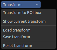
Transform drop-down menu in Zivid Studio
This allows you to visualize transformed point clouds in Zivid Studio, which can be useful when evaluating the point cloud quality. It also allows you to transform the point cloud to a chosen coordinate system, and save or export the transformed point cloud to file.
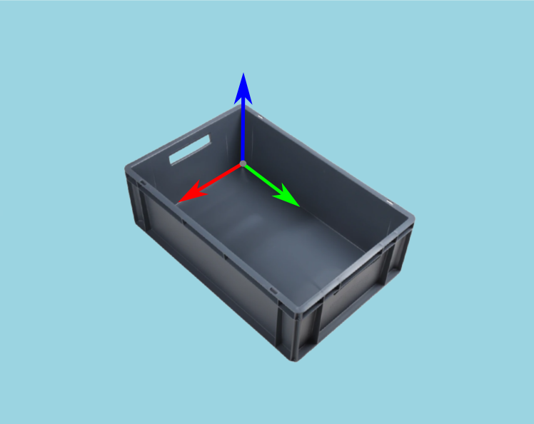
 (a) Point cloud in camera coordinate system
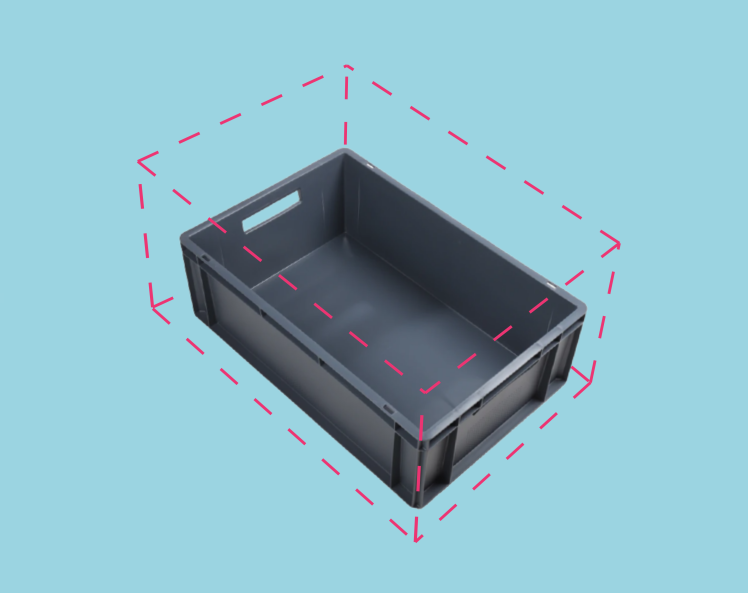
 (b) Point cloud in bin coordinate system
Point clouds are by default given in the camera coordinate system as in (a), but you can transform the point cloud to a more suitable coordinate system as in (b).
Transform in applications
This section covers applications with Zivid cameras and robots that utilize point cloud transformation. It describes typical coordinate systems in these applications and why it is helpful to transform the point cloud to these coordinate systems.
Picking
For a robot to pick the detected object in the point cloud, its coordinates must be transformed from the camera coordinate system to a coordinate system that the robot understands.
Robot coordinate system
We often want to transform object coordinates or the whole point cloud to the robot base coordinate system. This is explained in detail in the article How To Use The Result Of Hand-Eye Calibration.
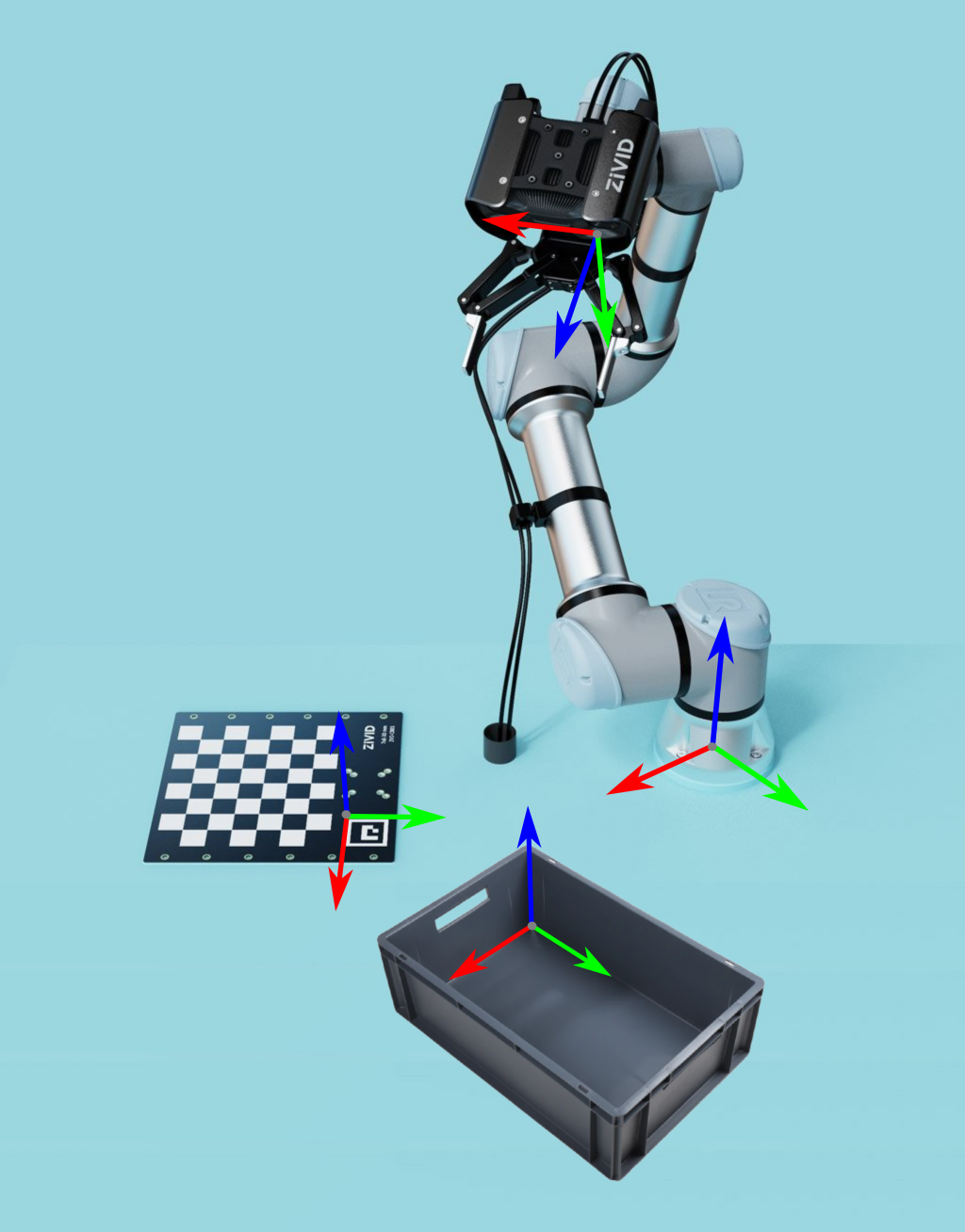
Plane coordinate system
The camera is often not parallel with the picking surface. Transforming the point cloud so that the point cloud z-axis matches the plane z-axis helps us better understand and interpret the point cloud data. Therefore, it is common to transform the point cloud to a coordinate system on the picking surface, such as the bin floor or conveyor belt.
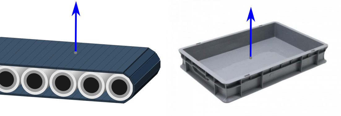
Bin coordinate system
There is another step that can help us to better understand the point cloud data and evaluate the picking performance. That is to align the x and y axes of the point cloud with the x and y axes of the bin.
Region of Interest
The camera field of view is often larger than our Region of Interest (ROI), e.g., a bin. Therefore, another reason to align bin axes with the point cloud axes is that it allows us to set a ROI box around the bin. We can then crop the point cloud based on the ROI to get only the points of the bin contents.
Tip
Smaller point clouds are faster to capture, and can make the detection faster and total picking cycle times shorter.
For an implementation example, check out ROI Box via Checkerboard. This tutorial demonstrates how to filter the point cloud using the Zivid calibration board based on a ROI box given relative to the checkerboard.
We also have ROI Box via ArUco Marker tutorial where instead of the checkerboard we use the ArUco marker.
Stitching
Point cloud stitching often involves transforming point clouds to a different coordinate system.
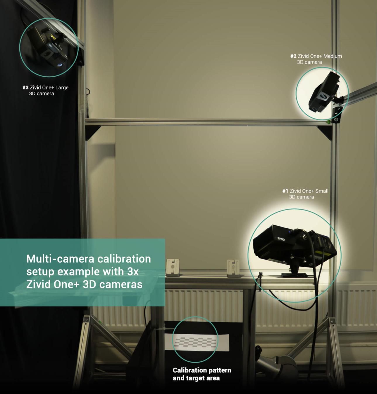
Multiple stationary cameras
Zivid Multi-Camera Calibration enables transforming point clouds from multiple cameras into the coordinate system of one of the cameras - the master camera. In multi-camera calibration, we often want to transform the stitched point cloud to a different coordinate system, such as the object coordinate system.
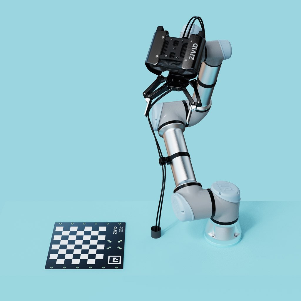
Single robot-mounted camera
Robot-mounted camera configuration allows stitching multiple point clouds taken with the same camera from multiple views. Once the point cloud is stitched in the master camera coordinate system, it is convenient to transform it to the object coordinate system.
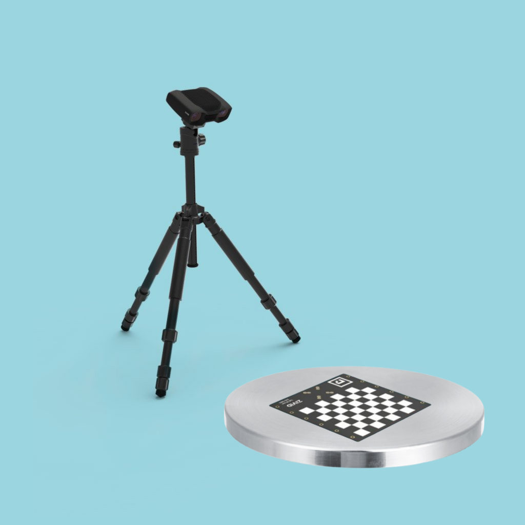
Single camera and turntable
If we know the pose of the turntable relative to the camera, we can stitch the point clouds and transform them to the turntable coordinate system.
Note
Multi-Camera Calibration is part of the SDK, and it uses the Zivid calibration board.
Pose estimation
Getting the pose of the camera relative to the robot base frame is done with the Hand-Eye Calibration. If we need a pose relative to an arbitrary user-defined coordinate system, we can place helpful accessories such as fiducial markers and checkerboards in the scene. Since we know their geometry, it is relatively straightforward to estimate their pose.
For an implementation example, check out Transform via Checkerboard. This tutorial demonstrates how to estimate the pose of the checkerboard and transform a point cloud using a 4x4 homogeneous transformation matrix to the checkerboard coordinate system. We also have Transform via ArUco marker tutorial where instead of the checkerboard we use the ArUco marker.
Version History
SDK |
Changes |
|---|---|
2.15.0 |
Transform in Zivid Studio is added, with API for getting the currently applied transformation matrix. |
2.0.0 |
Transform API is added. |