Any Robot + RoboDK + Python: Verify Hand-Eye Calibration Result Via Touch Test
Note
This tutorial has only been tested on UR5e and Yaskawa H10, and it only works with robots supported by RoboDK.
Introduction
Sometimes it is hard to measure how accurate the Hand-Eye Calibration is. Therefore, we created a Touch Test to verify accuracy easily. In this test, we use RoboDK to move the robot. This sample works for the results of both types of Hand-Eye Calibration, Eye-in-Hand and Eye-to-Hand. The Touch Test consists of placing the Zivid Calibration Object in the FOV of the camera, capturing it, and controlling the robot to touch it at a specific point. After touching, you can displace the Zivid Calibration Object and instruct the robot to touch it again. You can repeat this process as many times as you want. The only two limitations are the robot’s reach and the camera’s FOV.
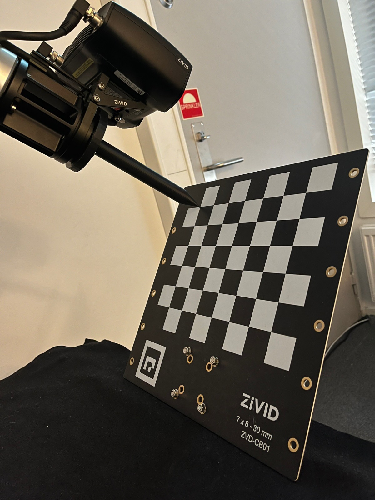
In the image below, you can see the expected result from the Touch Test.

Note
The accuracy of the touch depends on the Robot Calibration error, the Hand-Eye Calibration error, the TCP Calibration error, and Calibration Object Pose Estimation error.
Requirements
Zivid software installed, including Zivid Tools if on Linux.
Zivid-Python installed.
RoboDK software installed.
A robot that has a digital twin in the Robodk robot library.
A .yaml file containing the Hand-Eye transformation matrix resulting from a Hand-Eye Calibration.
A .yaml file containing the transformation matrix that defines the Pointed Hand-Eye Verification Tool.
Pointed Hand-Eye Verification Tool
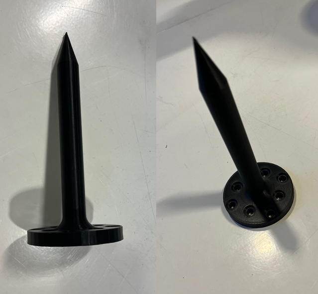
The Pointed Hand-Eye Verification Tool is used in this tutorial as the touching tool. This tool is compatible with UR5e (ISO 9409-1-50-4-M6) and the Yaskawa HC10 (ISO 9409-1-63-4-M6).
pointed-hand-eye-verification-tool.STL- CAD model in STL that can be used for 3D printing.pointed-hand-eye-verification-tool.STEP- CAD model in STEP that can be loaded to RoboDK.pointed-hand-eye-verification-tool.pdf- technical drawing.pointed-hand-eye-verification-tool.yaml- transformation matrix in YAML, required as one of the input arguments of the code sample associated with this tutorial.
The Pointed Hand-Eye Verification Tool is illustrated in the following image.
On-arm Mounts
In this tutorial, we assume using the Zivid On-Arm Mount Extender and the Zivid On-Arm Mount attached between the robot end-effector and the Pointed Hand-Eye Verification Tool. These mounts increase the distance between the robot end effector and the Pointed Hand-Eye Verification Tool. You can find the measurements added for each mount in the image below.
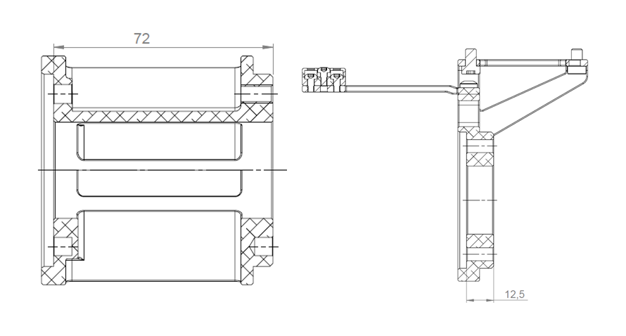
The on-arm-mounts.yaml file contains the transformation matrix of the two mounts installed between the robot end effector and the Pointed Hand-Eye Verification Tool.
For more details about the mounts, check out on-arm camera mount datasheet and on-arm mount extender datasheet.
If you already have the RoboDK environment set up and you are connected to your robot, you can jump to Create the Capture Pose for the Touch Test
Set Up RoboDK Environment
RoboDK .rdk files store information about the robot, target pose, and environment. The components in the .rdk file needed to perform the Touch Test are:
Robot model file (.robot)
One target pose (in the example demonstrated in this tutorial it’s named “touch_test_pose”)
Virtual model of robot’s environment (optional)
CAD model of the camera in use, e.g., Zivid 2 CAD file (optional)
CAD model of the Pointed Hand-Eye Verification Tool (optional)
Add Robot to RoboDK Environment
Start by opening the RoboDK program and adding the robot that will be used. To add the robot, open the library using the GUI by going to File -> Open online library. Find the robot that matches your model through this interface, hover over it with the mouse and choose Open. If the robot does not appear in the station, choose Download instead and drag and drop it into the .rdk environment. This is also described in the Select a robot RoboDK tutorial.
Connect to Robot through RoboDK
Warning
Depending on the brand of the robot being used, a driver setup might be required to connect to RoboDK. For help on this setup, check out the robot tips section in the RoboDK documentation. For example, here is the advice for ABB robots.
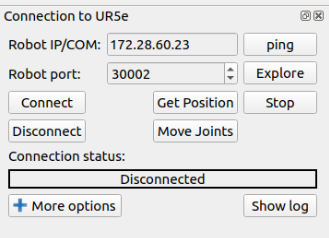
Before running the Touch Test script, it is first necessary to connect to the robot using the RoboDK interface. In RoboDK GUI navigate to Connect -> Connect Robot. This will open a side panel where you can insert the Robot IP and the port number.
Note
Most robots will have a remote mode on their control pendant or tablet. Make sure your robot is in remote mode to be able to establish the connection.
To connect to the robot you must know its IP address, it should be found/listed in the robot control pendant. Follow the steps for connecting to the robot for RoboDK. Another connection that should be verified is the port number. The default number that comes with the driver should work unless changes have been made previously.
Just click Connect and if the Connection status box is green, the RoboDK interface can be used to control the robot. If it is red instead, make sure that you have the right port number and IP address. If it is still red, check the Troubleshoot RoboDK chapter at the end of this tutorial.
Create the Capture Pose for the Touch Test
Learn how to create a target in RoboDK in order to save the Capture Pose for the Touch Test.
Creating poses using RoboDK can be approached in two ways:
Moving the robot physically to the desired poses using the pendant, then connecting through RoboDK and recording the poses
Moving the robot remotely through RoboDK to create and save the poses
Tip
If you are moving the robot through RoboDK and the robot is not moving fast enough or slow enough, check this link to set the robot speed in RoboDK. After setting the speed, remember to right-click on the program that you have created and mark Run on the robot and then right-click again and choose Run.
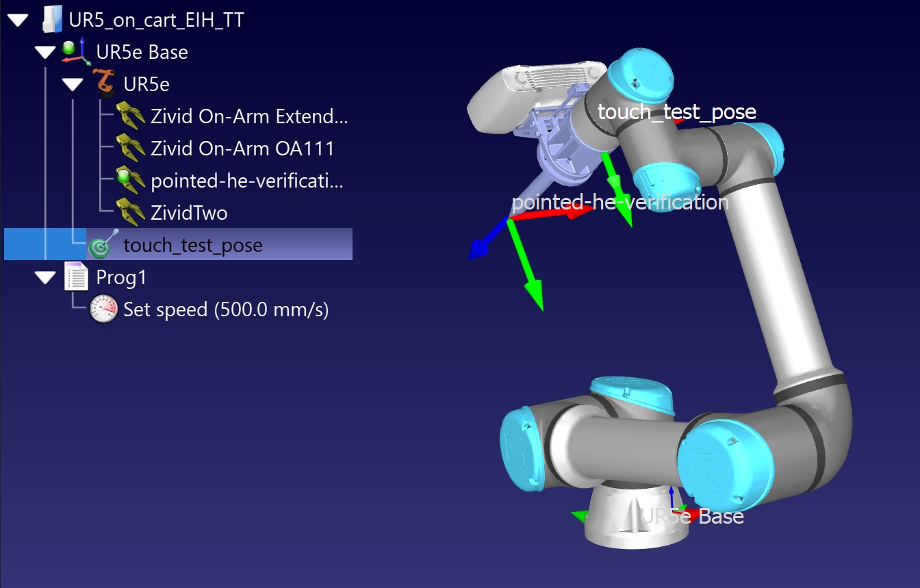
Before creating the Touch Test Capture Pose, you must consider where you plan to put the Zivid Calibration Object. If Eye-in-Hand, ensure it will be in the FOV of the camera. If Eye-to-Hand, ensure that the robot will not block the view of the Zivid Calibration Object. Only one pose is needed for the Touch Test. You can see illustrated below how it looks in RoboDK.
Tip
To have control of the robot configurations used, ensure the saved targets are joint targets, not cartesian targets. Right-clicking on a target in RoboDK and choosing a joint target will transform the pose into a joint target. This will also change the target symbol color from red to green.
Run the Touch Test
Before running the script, it is required to have the .rdk file open and be connected to the robot. The script can be found in the Zivid Python Samples; it takes the following command line arguments, as shown below.

type_group.add_argument("--eih", "--eye-in-hand", action="store_true", help="eye-in-hand configuration")
type_group.add_argument("--eth", "--eye-to-hand", action="store_true", help="eye-to-hand configuration")
parser.add_argument("--ip", required=True, help="IP address of the robot controller")
parser.add_argument(
    "--target-keyword",
    required=True,
    help="RoboDK target name representing a robot pose at which the calibration object is in the field of view of the camera",
)
parser.add_argument(
    "--tool-yaml",
    required=True,
    help="Path to YAML file that represents the Pointed Hand-Eye Verification Tool transformation matrix",
)
parser.add_argument(
    "--mounts-yaml",
    required=False,
    help="Path to YAML file that represents the on-arm mounts transformation matrix",
)
parser.add_argument(
    "--hand-eye-yaml",
    required=True,
    help="Path to the YAML file that contains the Hand-Eye transformation matrix",
)
subparsers = parser.add_subparsers(dest="calibration_object", required=True, help="Calibration object type")
subparsers.add_parser("checkerboard", help="Verify using Zivid calibration board")
marker_parser = subparsers.add_parser("marker", help="Verify using ArUco marker")
marker_parser.add_argument(
    "--dictionary",
    required=True,
    choices=list(zivid.calibration.MarkerDictionary.valid_values()),
    help="Dictionary of the targeted ArUco marker",
)
marker_parser.add_argument(
    "--id", nargs=1, required=True, type=int, help="ID of ArUco marker to be used for verification"
)
The script runs in the following steps:
The robot moves to the Capture Pose previously defined.
The user is asked to put the Zivid Calibration Object in the FOV and press Enter.
The camera captures the Zivid Calibration Object and the pose of the touching point is computed and displayed to the user.
When the user presses the Enter key, the robot touches the Zivid Calibration Object at a distinct point.
Upon pressing the Enter key, the robot pulls back and returns to the Capture Pose.
At this point, the Zivid Calibration Object can be moved to perform the Touch Test at a different location.
The user is asked to input “y” on “n” to repeat or abort the touch test.
Script walk-through
For the RoboDK Hand-Eye Calibration verification script to be functional it requires three additional Python files.
robodk_tools.py is used to configure the robot.
save_load_matrix.py is used to save and load matrices to or from YAML files.
The script runs through the following steps respectively:
Connect to robot
Firstly, we connect to the robot using the IP address.
We then get a rdk object used to establish a link with the simulator and a robot object containing various robot configuration parameters.
Set robot speed and acceleration
The last step of the robot configuration is defining the speed and acceleration of the robot.
Load Pointed Hand-Eye Verification Tool transformation matrix
The transformation matrix that defines the Pointed Hand-Eye Verification Tool is then loaded.
Define TCP transformation matrix
Then we need to define the tool center point (TCP).
Firstly the program will check if the user provided a .yaml file containing an on-arm mounts matrix.
If the user does not provide any on-arm mounts matrix, we assume the Pointed Hand-Eye Verification Tool is directly attached to the robot’s end effector.
Therefore, the TCP matrix is equivalent to the Pointed Hand-Eye Verification Tool matrix.
if user_options.mounts_yaml:
    print("Loading the on-arm mounts transformation matrix from a YAML file")
    flange_to_tool_base_transform = load_and_assert_affine_matrix(user_options.mounts_yaml)

    flange_to_tcp_transform = flange_to_tool_base_transform @ tool_base_to_tool_tip_transform
else:
    flange_to_tcp_transform = tool_base_to_tool_tip_transform
Move to Capture Pose
The robot moves to the capture_pose, which is obtained from the .rdk file that is open while running this sample.
capture_pose = get_robot_targets(rdk, target_keyword=user_options.target_keyword)
if not capture_pose:
    raise IndexError(
        "The list of poses retrieved from RoboDK is empty...\nMake sure that you have created a Capture Pose and that you introduced the right keyword for it."
    )
robot.MoveJ(capture_pose[0])
Place the Zivid Calibration Object
The next step is to ensure the user has placed the Zivid Calibration Object in the FOV of the camera.
Zivid Calibration Object Detection and Pose Estimation
After pressing Enter, the Zivid Calibration Object is captured and its pose in the camera frame is estimated.
Transform the Zivid Calibration Object Pose from Camera to Robot Base Frame
To understand the maths behind this transformation, check out Hand-Eye Calibration Solution.
Get the Touch Pose
Since the touch pose we control the robot to move to is the end-effector (flange) pose, we need to take the TCP into consideration.
Get the Approach Pose
We define the approach pose as an offset from the touch pose in the Z axis, arbitrarily chosen to be -140 mm.
Touch the Zivid Calibration Object
Before approaching and touching the Zivid Calibration Object, the calculated touch pose is displayed to the user.


The user can then press Enter to allow the robot to perform the touch.
To touch the Zivid Calibration Object, the robot first moves to the approach pose with joint movement. Then it moves in a straight line to the touch pose. At this point, the user can get close to the Zivid Calibration Object and visually inspect the accuracy of the performed touch.
Move Away from the Zivid Calibration Object
The program expects the user to press Enter for the robot to move away from the Zivid Calibration Object back to the Capture Pose.
Touch the Zivid Calibration Object Again
At this point, the Zivid Calibration Object can be moved to perform the Touch Test at a different location within the FOV of the camera. The user is asked to input “y” or “n” to repeat or abort the touch test.
Troubleshoot RoboDK
Robot Moving to Different Configuration than Intended
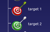
To have a repeatable Touch Test process, use joint targets because the robot will always assume the same configuration. Using cartesian targets allows the robot to choose the configuration, which can lead to collisions. In the image below, you can see two targets, the
target 1represented with a red color and thetarget 2colored green. The red color means the target is cartesian, and the green means it is a joint target.
Connect Through Firewall on windows
Note
This method was tested on Windows 10.
Check driver blockage
When connecting to a computer running Windows be aware that the firewall can prevent the connection to the robot. One option is to disable the firewall completely, but this is not recommended as it will leave your system vulnerable.
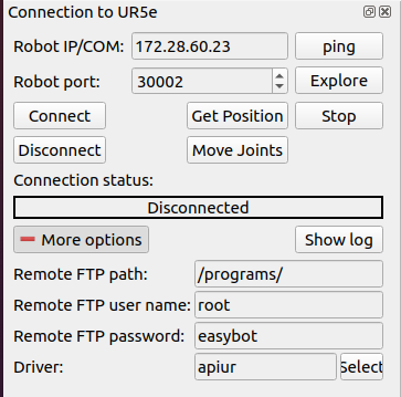
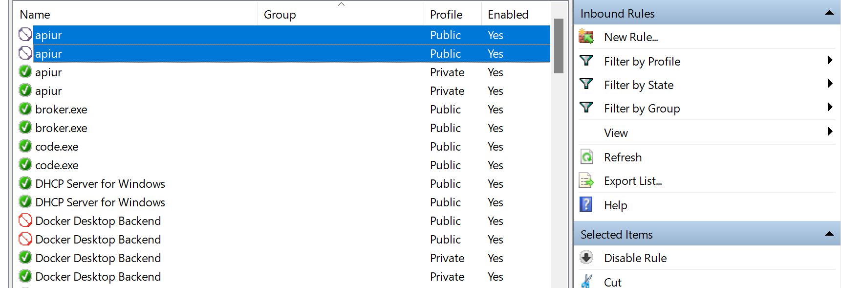
Instead, you can add a new rule to your windows firewall to allow communication only for the driver and IP address of the robot you use. To find these two attributes expand the connect to robot panel by choosing more options. In this case, the driver is apiur.
Go to the Windows Defender Firewall on your system and go into the Advanced settings. This will lead you to definitions of the firewall rules. Here the inbound rules can be changed to allow communications with the driver needed to control the robot.
Check in the inbound rules if the robot driver has a blocked sign. If the driver is blocked, disable this rule; otherwise, the firewall blocks communication.
Once this rule is disabled, check if the RoboDK software can connect to the robot. If you can still not connect to the robot, you need to make a rule that specifically allows the driver to communicate with the robot.
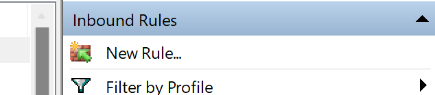
Create a new inbound rule
By clicking New Rule… you create and define a rule that allows communication between your computer and the robot.
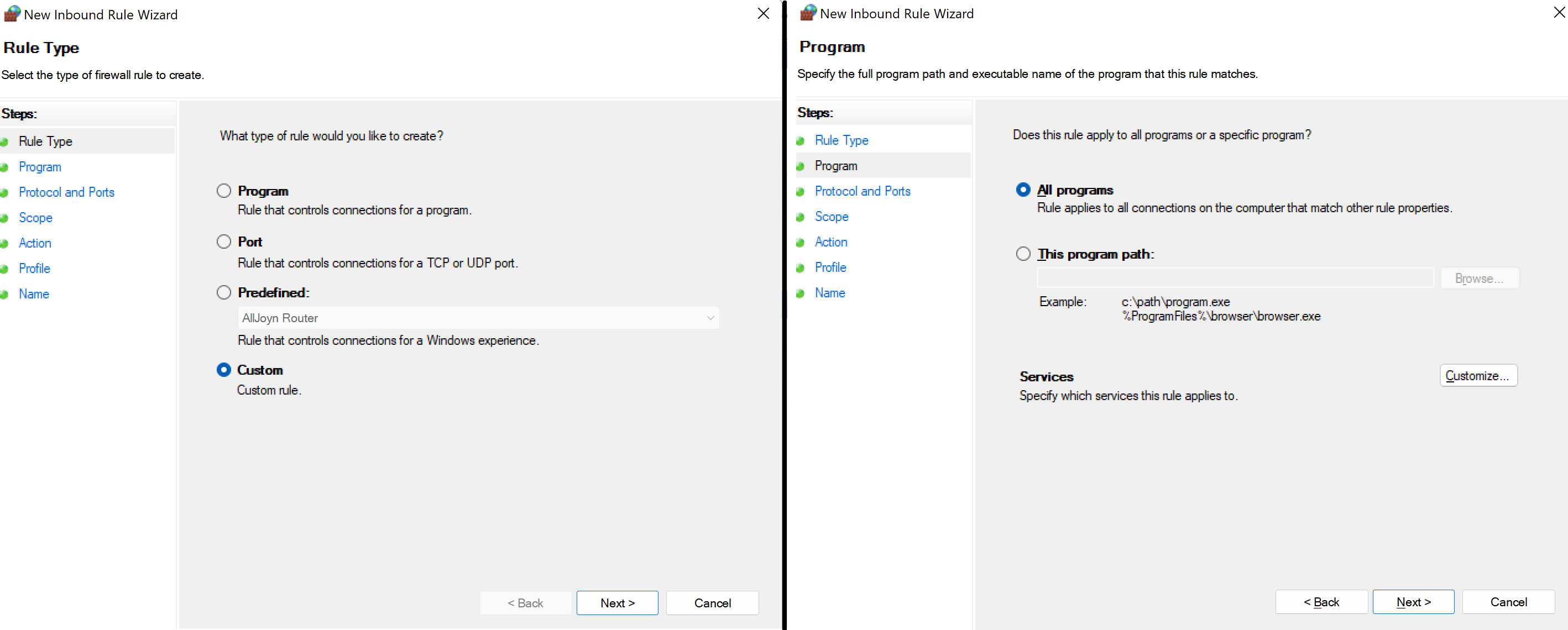
To begin with, you need to choose the option Custom on the first page and All programs on the second. you can find it illustrated below.
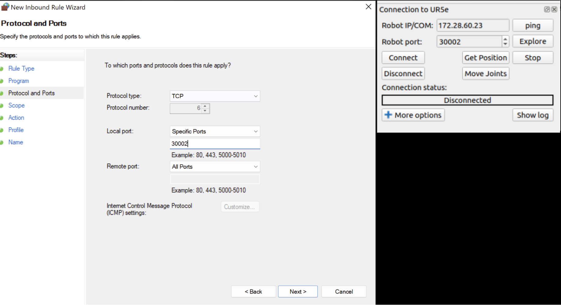
On the next page you need to choose the TCP as protocol, then choose a specific local port and insert the number of the port matching the one in RoboDK.
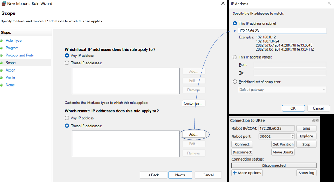
The next step is setting the IP address. Under Which remote IP address does this rule apply to?, choose These IP addresses. Then click on Add and set the IP that matches the one in RoboDK.
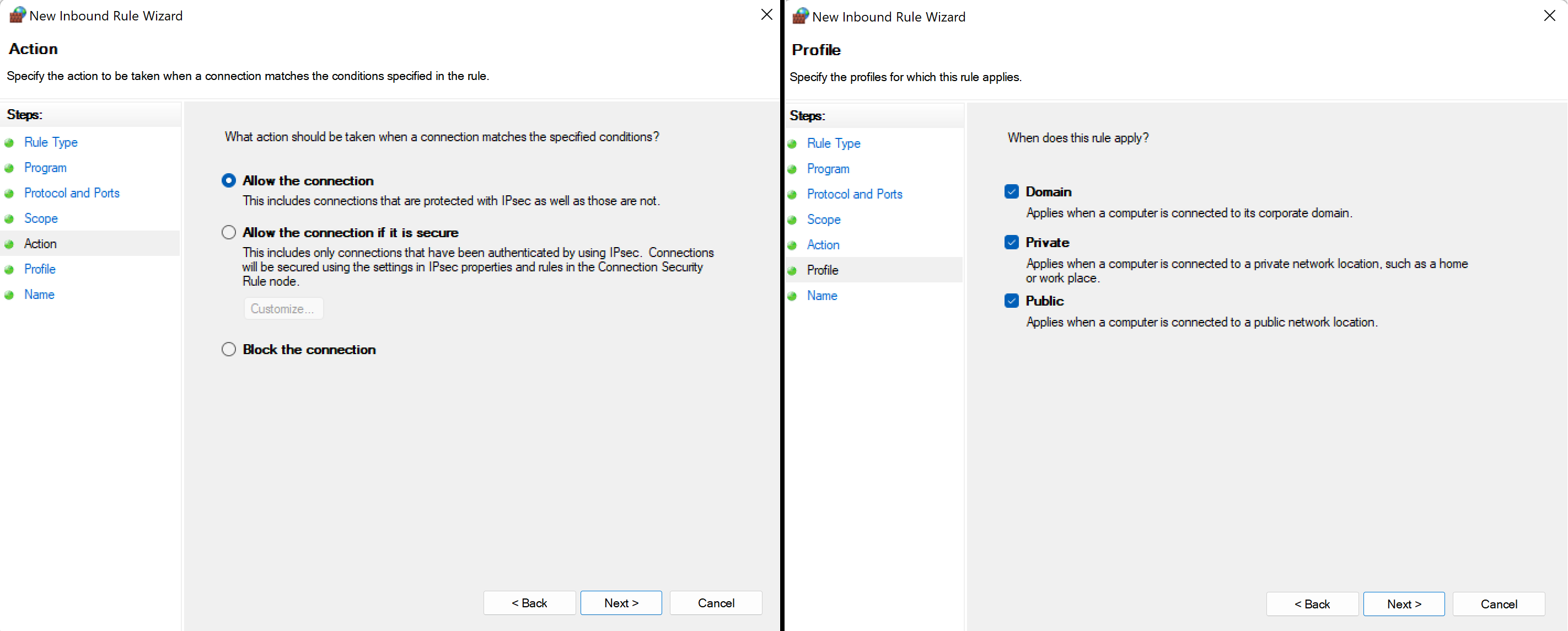
After hitting OK and Next, choose Allow all connections and on the next page, check all boxes.
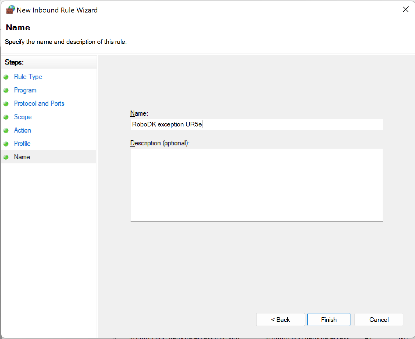
Finally, just choose a proper name for the rule, click Finish and you are good to go!